A general question to those that know more ...
the schematic shows the suppressor grid is floating - can that be a cause of instability? Normally it would be tied to the cathode.
A photo of the underside would be interesting.
the schematic shows the suppressor grid is floating - can that be a cause of instability? Normally it would be tied to the cathode.
A photo of the underside would be interesting.
Not very likely;Could I add to that list the possibility of a dry earth joint at the cathode?
when you disconnect the cathode resistor from ground your meter should read a high voltage near B+ at the cathode;
unless your meter ground is also broken ...
I would start with the screen resistors ...

Just sloppy draftsmanship: the original KT66 is a true tetrode, no G3 inside, pin 1 is not connected.... the schematic shows the suppressor grid is floating...
There could be some concern nowadays: everybody slaps any labels on any tubes.
The meter are installed as the photo:-Not very likely;
when you disconnect the cathode resistor from ground your meter should read a high voltage near B+ at the cathode;
unless your meter ground is also broken ...
Yellow to cathode side of the cathode resistor, black to cathode earth. Red to power supply (+6v) and black to power supply earth. As indicated, power supply earth and cathode earth are connected together.
(Just though to double check so we can rule this out, although easy to double check anyways)
Attachments

Hi all,
Having replaced the screen resistors, I discovered that the problem was actually the voltage meter reading the cathode, it was shorting which caused the cathode voltage to drop. So, I took the meter out, powered up and took some voltages measurements.
At 140v and 180v AC, both sets of measurements were spot on.(I move up in small increments).
At 180v AC, B+ was 325v, 6n1p plate 165v, KT66 plate 318v, KT66 Cathode 24v, all looking good and as previously measured when all was well.
I then increased AC voltage to 200v and then both cathodes dropped from 24v down to 2.5v instantly, so switched off.
Later I tried again but as I got to 140v AC, B+ was only 66v (not 325v), KT66 plates were only 56v (not 318v), so switched off again.
I then noticed that the rectifier (5u4G) was extremely hot to the touch, the test was only undertaken for 30 seconds or so, wasn't expecting to be that hot.
Started off fine, then something has happened to make B+ drop all of a sudden and the rectifier tube to get really hot. The tube is newish.
Would any of you wonderful experts reading this have any thoughts? I really so appreciate this all.
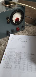
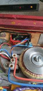
Just to add to misfortune, the attached photo shows my Variac (and measurment notes) you'll notice the little red meter in the centre of the voltmeter (not in use). Before my current test, last week, I started another test and there was a flash/spark at the input to the amplifier (2nd photo) taking the variac apart I noticed that one of the wires out of the meter was out of its socket (and was live) which caused the flash 🙈
Having replaced the screen resistors, I discovered that the problem was actually the voltage meter reading the cathode, it was shorting which caused the cathode voltage to drop. So, I took the meter out, powered up and took some voltages measurements.
At 140v and 180v AC, both sets of measurements were spot on.(I move up in small increments).
At 180v AC, B+ was 325v, 6n1p plate 165v, KT66 plate 318v, KT66 Cathode 24v, all looking good and as previously measured when all was well.
I then increased AC voltage to 200v and then both cathodes dropped from 24v down to 2.5v instantly, so switched off.
Later I tried again but as I got to 140v AC, B+ was only 66v (not 325v), KT66 plates were only 56v (not 318v), so switched off again.
I then noticed that the rectifier (5u4G) was extremely hot to the touch, the test was only undertaken for 30 seconds or so, wasn't expecting to be that hot.
Started off fine, then something has happened to make B+ drop all of a sudden and the rectifier tube to get really hot. The tube is newish.
Would any of you wonderful experts reading this have any thoughts? I really so appreciate this all.
Just to add to misfortune, the attached photo shows my Variac (and measurment notes) you'll notice the little red meter in the centre of the voltmeter (not in use). Before my current test, last week, I started another test and there was a flash/spark at the input to the amplifier (2nd photo) taking the variac apart I noticed that one of the wires out of the meter was out of its socket (and was live) which caused the flash 🙈
Attachments
Last edited:
Given your problems with 'wires out of sockets' and 'things shorting' and nonsensical voltages, it sounds like you may have wired literally anything up wrong / badly. Who knows what's wrong or what may be damaged. We don't even have a full schematic to go off.
Last edited:
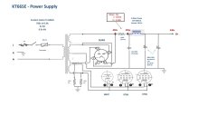
Hi Merlinb, thank you for your reply (my, not very good, Schematics attached).
My apologies for being a novice but I really do appreciate your advice and I hope I am not an annoyance to the community.
I'll try to be concise.
1) I started to undertake test voltages and I do this at 140v, 180v, 200v, then 230v AC.
2) 140v and 180v measured as expected (please refer to the above photo with the variac). The same as when the amp was working correctly, so all OK.
3) When I increased AC to 200v, B+ dropped suddenly from 325v to 66v, KT66 plates from 317v to 56v etc.
4) Re-tested a little later, but this time at AC 140v, B+ was only 66v and not as previous/expected 325v.
4) Rectifier tube was very hot, KT66's were cold (had a plate voltage of 56v and 2.5v cathode).
So, all was well up to 180v AC, but not after 200v and not since.
I think (think) I could have shorted the rectifier, maybe even the Mains TX plus all the power supply caps?
The short was a daft error, but the amps iec socket flashed/sparked and this was before the tests.
Attachments

Last edited:
How can you possibly get over 300V with only 140V supply?4) Re-tested a little later, but this time at AC 140v, B+ was only 66v and not as previous/expected 325v.
The IEC socket flashed? What are you doing to this poor amplifier??the amps iec socket flashed/sparked and this was before the tests.
(Correction) The mesurement sheet shows B+ at 325v and this was at 180v AC.How can you possibly get over 300V with only 140V supply?
At 140v AC, B+ was 272v.
Sorry (!)The IEC socket flashed? What are you doing to this poor amplifier??
Last edited:
I suspect the rectifier too. I would replace the rectifier with 2 solid state diodes. Even you prefer the tube rectifier, diodes should be added in series with each plate of the rectifier.I think (think) I could have shorted the rectifier, maybe even the Mains TX plus all the power supply caps?
That's great, thanks jxdking.I suspect the rectifier too. I would replace the rectifier with 2 solid state diodes. Even you prefer the tube rectifier, diodes should be added in series with each plate of the rectifier.
I'll order some 1N4007 diodes, place them in series with the plates, cathode end to rectifier plates and order a new rectifier.
Would you consider it necessary to replace the 10uf cap, and perhaps the remaining PS caps or just the rectifier?
So where you powering the voltmeters straight from the cathodes? That's likely gonna damage the meters, they're only rated for 40V (and those are Chinese volts). Also the meter is gonna drain variable current from the output tube.
Last edited:
I think the caps are fine as long as they were installed in the correct polarity. If the short happened in the caps, you would have seen the magic smoke/steam.Would you consider it necessary to replace the 10uf cap, and perhaps the remaining PS caps or just the rectifier?
May I offer my most grateful thanks and appreciation for your advice 🙏I think the caps are fine as long as they were installed in the correct polarity. If the short happened in the caps, you would have seen the magic smoke/steam.
Meters powered from an independent supply, attachments to the cathodes for measurement only.So where you powering the voltmeters straight from the cathodes? That's likely gonna damage the meters, they're only rated for 40V (and those are Chinese volts). Also the meter is gonna drain variable current from the output tube.
I believe so, it was great for 2yrs with no problems.Is that supply reliable and done properly? I mean, bad luck is following you around
I dont think it's bad luck, just me being a bit stupid/clumsy and also not following correct maintenance procedures.
The two years it work perfectly was during lock-down and it was on every day for around 12hrs (not continuous).
One of the output tubes went into voltage runaway and caused catastrophic failure. Hence the voltage meters on the cathodes. That was over 10 months ago and I'm only just about, hopefully, to repair it.
I was going to check these Friday, (work in the office Tuesdays, Thursdays) and post readings then. Are you thinking about Mains Tx?What are the voltages on the rectifier and output tube sockets without all the tubes fitted?
Also, how does it look after returning the rectifier tube, with no output tubes?
I'm a little reluctant to put the rectifier back in Hector, it was very hot after 30 seconds or so and the KT66'S were cold (I'll check their heaters Friday).
As stated in #27, everything was fine upto 180v AC, then at 200v AC B+ dropped.
How are the meters attached? Reading the voltage drop across the cathode bias resistors?
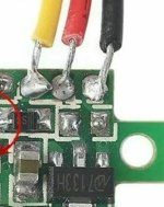
Meters are attached as diagram #24. Separate power supply (12v) to power the meters and then yellow wire to cathode side of resistor, black wire to both earth side of cathode resistor and to power supply ground. Worked fine for months. The connections are poor design which why it shorted.
Attachments
- Home
- Amplifiers
- Tubes / Valves
- Varying Cathode Bias voltage question