On top of the amp? A lot of meaning for me behind those, and the whole amp generally. Divine Mercy veneration. 🙏Not related to the main problem but what do those LEDs bring to the party????🙂
Kool, but aside from their appearance is there any measurable
improvement in the amp performance wise???
Just after the Earth cooled in 1968 we could buy multi junction devices.
both Germanium & Silicon. I don't recall any audio circuit using them,
but some power conversion ccts, AC to DC could put them to use.
Add to that the Unijunction Transistor used extensively in SCR control circuits. 👍
Attachments

😂
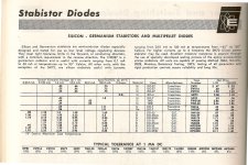
Not sure about measurable improvements, or where a Stabistor would be located in my circuit, but most of those, in the UK at least, appear to be unobtanium. 👍
Not sure about measurable improvements, or where a Stabistor would be located in my circuit, but most of those, in the UK at least, appear to be unobtanium. 👍
It is just to get back to a baseline with the minimum variables. If the unloaded voltages look OK on the pins (assuming the power supply caps are not exceeding their voltage limits because of the unloaded voltages) then you can start to decide whether it is the transformer that is an issue or something else.I was going to check these Friday, (work in the office Tuesdays, Thursdays) and post readings then. Are you thinking about Mains Tx?
Instead of adding the rectifier back, do you have a couple of diodes that you could tack in place as an experiment to eliminate the rectifier tube? Then you have the option of testing the amp with some load and no rectifier tube, to eliminate that.
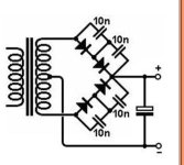
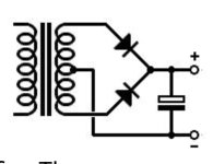
Well, I will have only those that I have ordered, 1N4007, but I won't be able to test with those at full voltage (230v AC) unless I wire two in series with some ceramic caps as attached photo clippet from the excellent ValveWizard.co.uk website. The second photo, using 1n4007, is recommended only up to 290-0-290v (mine is 375-0-375v)Instead of adding the rectifier back, do you have a couple of diodes that you could tack in place as an experiment to eliminate the rectifier tube?
Test process then:
1) pull all tubes and test Mains transformer voltages at (empty) rectifier pins 4 and 6. (should be up to 375v)
2) test all heaters.
3) install 1n4007 diodes as below photos, say the 2nd with only 2 diodes, and test up to 140v ac with the driver and output tubes in place.
These 3 steps should give me the answer, I'm hoping, obvs, all 3 are OK then it's the tube rectifier.
Max unloaded voltage is 530v and all caps are rated 600/630v.
Attachments
Hi Guys,
Almost there, after a busy patch at work.
Quick question, anyone have any issues with the attached sketch, in particular, using BY255's instead of 1n4007?
Read that 1N4007's are optimal.
BY255 are better rated.
I have both, and enough to run either in series, with 10nf parrallel caps, if required using a 375-0-375v transformer.
Thanks
Attachments

- Home
- Amplifiers
- Tubes / Valves
- Varying Cathode Bias voltage question