Sim I refer to, that had linearity issues and lowish in
both gain and headroom, was with 6DJ8 driving 6L6.
Standard octode topology, no help from sand. Either
I've misunderstood something I was supposed to do
differently? Or it simply hates me. I'm OK with that...
Negative rail and long tail would have fixed headroom.
That may be 90% all really needed. Low gain isn't an
issue, since you still need a phase splitter. And yet
another LTP up front the obvious solution for both.
-------
I think I can throw two piece of sand LTP inbetween,
and in so doing, fix Octode problems quite nicely. The
sand doesn't "do" anything except hold the triode at
nearly fixed current, and force the Pentode to act as
the triode dictates. Any currents passed by the sand
are either DC, or merely those of the screen pull down,
returned to the plate after a proper phase reversal.
Since Octode as originally conceived eats up a lot of
unnecessary tOObage to no greater result than Millet
RedBoard style plate to plate feedback, why bother?
But add sand: now screen currents suddenly become
a recoverable loss, plate efficiency effectively goes up.
It finally does something RedBoard can't claim. Mabey
now I care? Its too early to say for sure.
When I can give you a full working simulation with all
mystery parts defined, then perhaps we can put this
theory to the test. Maybe by then, someone will post
the original bill of materials and schematic to compare.
Last edited:
Kenpeter
I'll scan the schematic and email it to you, or post it to photobucket and I can share it that way...
Then we can be sure we're all looking at the same schematic. FWIW, I plan to use 6n23Pi for my 6922. I have MWT 6V6GTs on the way, but also have GE 6V6GTs.
I'll scan the schematic and email it to you, or post it to photobucket and I can share it that way...
Then we can be sure we're all looking at the same schematic. FWIW, I plan to use 6n23Pi for my 6922. I have MWT 6V6GTs on the way, but also have GE 6V6GTs.
The two transistor version is broken too.
I've messed up and created two separate
and conflicting bias references for DC.
I'm sure the answer will come to me.
Would be easy except I went overboard
and had to make it a direct coupled...
I've messed up and created two separate
and conflicting bias references for DC.
I'm sure the answer will come to me.
Would be easy except I went overboard
and had to make it a direct coupled...
The related article at TubeCad implies that using a triode to drive a pentode is a bad idea (link) - is this a common thought - or only when connecting driver plate to output plate?
There is something very interesting in the TubeCad article however - this final diagram:
uses a sort of long tailed pair but with the input triode plate tied to the output - the LTP allows a capacitor-less feedback into the first stage, giving two-stage feedback sans capacitor.
I'm interested in this concept (capacitorless feedback over 2 stages (to reduce impedance seen by OPT)) so was wondering if anyone here has tried an 'octode' topology over a LTP triode and/or a single triode driving a pentode.
For context I'm re-wiring a GU50 based SE amplifier and currently have a 6n6p driving a GU50 in triode mode, but am now ready to switch the GU50 into pentode mode (250V at g2) to increase the output.
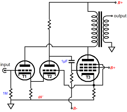
Here is the schematic:
An externally hosted image should be here but it was not working when we last tested it.
Re:
"The related article at TubeCad implies that using a triode to drive a pentode is a bad idea (link) - is this a common thought - or only when connecting driver plate to output plate? "
I'm guessing that the thinking there for a single triode plate feedback driver was that the triode transfer curve and the pentode transfer curve are of similar nature and adding together (compounding), rather than cancelling. This could be fixed up by just using a CCS cathode load on the single triode case (leads to a constant voltage drop from g1 to cathode, so the transfer of the triode is nulled out). Some issues come up though. The triode Mu needs to be well below the forward gain of the loaded pentode (for the single triode case), or there will be no effective neg. feedback. The transfer curve compounding issue above may also be somewhat irrelevant, since the feedback thru the triode plate also suffers a similar non-linear transfer as the g1 drive signal, so this may largely cancel the g1 curve effect.
Re:
"a sort of long tailed pair but with the input triode plate tied to the output - the LTP allows a capacitor-less feedback into the first stage, giving two-stage feedback sans capacitor.
I'm interested in this concept (capacitorless feedback over 2 stages (to reduce impedance seen by OPT)) "
Umm, well, the standard octode, as well as the modified version, both have the 1 uF cap to the pentode grid. So both are cap coupled. With 3 stages in the feedback loop, it also fits the standard definition of global feedback. The modified version with V2's grid to the pentode cathode connection will raise output impedance considerably, not what you want normally.
Ken's comments are spot on here. The Octode needs either a tail to B- or a CCS tail. The voltage amplifier V2 really wants to be a pentode. The higher the gain of V2, the less the current variation of V1, and so the less variation of it's Mu. As originally configured, the Octode should do a good job of producing P-P sound from a SE amplifier. ( due to the symmetrical current variation thru V1 and V2 producining odd harmonics, unless the tail resistance is specifically tuned to null the 3rd harmonic) And some biasing adjustment is needed for V2's presently grounded grid (for non matched tube sections).
Last edited:
"Here is the schematic:......"
Huh!! Sure you've got the right schematic? Thats not even remotely similar to what we've been discussing! No plate feedback, triode and pentode outputs in parallel. The pentode's are just providing current boost to the triodes.
Ummm, this is almost the standard old fashioned paralleling of triodes and pentodes, mentioned in RDH4. It works fine. The twist here is it's using Yundt's scheme to combine a voltage amplifier with a current amplifier so that current from the voltage amplifier is minimised. I've mentioned this scheme numerous times in the past on DiyAudio. Yundt has a thesis paper on this setup, and also published an article a long time back in IEEE Power Electronics ... magazine.
Last edited:
"Here is the schematic:......"
Huh!! Sure you've got the right schematic? Thats not even remotely similar to what we've been discussing! No plate feedback, triode and pentode outputs in parallel. The pentode's are just providing current boost to the triodes.
Ummm, this is almost the standard old fashioned paralleling of triodes and pentodes, mentioned in RDH4. It works fine. The twist here is it's using Yundt's scheme to combine a voltage amplifier with a current amplifier so that current from the voltage amplifier is minimised. I've mentioned this scheme numerous times in the past on DiyAudio. Yundt has a thesis paper on this setup, and also published an article a long time back in IEEE Power Electronic ... magazine.
That is the schematic scanned from page 40 of the 1/10 issue of aX that was left out of the original article. To my understanding JRB's Octode blog page was not a direct copy of AJ's schematic.
But perhaps aX screwed up again as I don't see how the 6L6 is driving the EL34s as described in the aX article or JRB's further discussions on TCJ. I only see the triode output tied to the OPT... In parallel as you described.
Last edited:
"Here is the schematic:......"
Huh!! Sure you've got the right schematic? Thats not even remotely similar to what we've been discussing! No plate feedback, triode and pentode outputs in parallel. The pentode's are just providing current boost to the triodes.
Ummm, this is almost the standard old fashioned paralleling of triodes and pentodes, mentioned in RDH4. It works fine. The twist here is it's using Yundt's scheme to combine a voltage amplifier with a current amplifier so that current from the voltage amplifier is minimised. I've mentioned this scheme numerous times in the past on DiyAudio. Yundt has a thesis paper on this setup, and also published an article a long time back in IEEE Power Electronics ... magazine.
You wouldn't happen to have links to PDFs or copies of those articles would you?
So if I use that schematic and change the 6L6s and EL34s to 6V6s, will it sim correctly? I suspect I'll have to change resistor values and tweak caps, but will it get me close off the bat?
Re:
"You wouldn't happen to have links to PDFs or copies of those articles would you?"
http://www.diyaudio.com/forums/tubes-valves/53198-advances-tube-amp-design-5.html#post595103
http://www.diyaudio.com/forums/tubes-valves/53198-advances-tube-amp-design-6.html#post595503
IEEE Xplore - Sign In
DSpace@MIT : Series parallel connected composite amplifiers
Univ. of Colorado had the IEEE article online, I'm trying to find it again. It's a well known paper in the power electronics field. (audio circuit publications were a tiny part of the power amplifier literature, entire shelves of journals on power electronics and circuit design at any Univ. Library)
Last edited:
There is something very interesting in the TubeCad article however - this final diagram:
uses a sort of long tailed pair but with the input triode plate tied to the output - the LTP allows a capacitor-less feedback into the first stage, giving two-stage feedback sans capacitor.
It is a "current drive" amp, some people believe that speakers sound much better driven such a way. However, a frequency response equalization is needed.
"So if I use that schematic and change the 6L6s and EL34s to 6V6s, will it sim correctly? I suspect I'll have to change resistor values and tweak caps, but will it get me close off the bat? "
You need to check the B+ voltages for compatibility with the 6V6. 6V6 has rather lower plate and screen limitations that the 6L6 or EL34. Then check on the grid bias voltages for reasonable operating currents.
-----------
The earlier "Octode" diagram has thrown us for a loop it seems. T1 and T2 were considered as dual triodes in LTP configuration, with T1 used for inverted plate feedback. Seems the actual intention of the Octode design was to sample the T1 (as a power) triode operating current and amplify that to control the pentode. With sufficient gain, the pentode lowers the apparent loading on the triode (higher Z load). V5 and V6 here would still benefit to be pentodes rather than triodes for higher loop gain. And although it might seem that the power triode and pentodes are just operating in parallel isolated worlds, there is real feedback here. (Yundt analyzed the criteria for stability in this configuration) The Hi-Z pentode output current lowers the loading on the power triode (triode sees higher Zload), causing R8 and R9 current pickoff signals to reduce the drive to the pentodes. The higher the gain of V5 and V6, the more the pentodes carve out more load current from the power triodes.
One thing that needs fixing here now is the R14 tail resistor. Common mode currents are being picked up as well as differential currents from the triodes and amplified by V5 and V6. Then the pentodes multiply it further. Common mode AC currents in P-P are pure distortion in Class A (odd harmonics). So a CCS would help eliminate them. Probably doesn't make much difference in Class AB though.
By the way, what mode of operation (class A or AB) is this supposed to be in anyway?
So with that new (and totally different) perspective, there is some similarity between the designs. All were intended as composite amplifiers a'la one of Yundt's designs, the V/I composite amplifier. Actually, Yundt just pulled all the composite design possibilities together in his papers for analysis of performance. He mentions in his papers that most were extracted from previous published sources. So there is some (likely tube) predecessor(s) back even further. (maybe he gave some references) The audio designer's never seemed to keep up with the academic journal literature, almost always using the same tired old cheapo designs.
Last edited:
A CCS in place of R14, in Class AB or B, won't work, since the ON side will be stuck at the full CCS current.
Also, the power pentodes could be replaced by Mosfets connecting directly to the secondary side of the transformer (ground the CT of the secondary, use LV power for them). Then you can use a much smaller OT. The triodes still control the voltage as long as you don't put too much gain in the loop (they need some load current to sense load Z variation). And reduced load current through the OT can reduce the problems from leakage L in the OT also. I think I mentioned this idea once before on DiyAudio.
Also, the power pentodes could be replaced by Mosfets connecting directly to the secondary side of the transformer (ground the CT of the secondary, use LV power for them). Then you can use a much smaller OT. The triodes still control the voltage as long as you don't put too much gain in the loop (they need some load current to sense load Z variation). And reduced load current through the OT can reduce the problems from leakage L in the OT also. I think I mentioned this idea once before on DiyAudio.
Last edited:
"So if I use that schematic and change the 6L6s and EL34s to 6V6s, will it sim correctly? I suspect I'll have to change resistor values and tweak caps, but will it get me close off the bat? "
You need to check the B+ voltages for compatibility with the 6V6. 6V6 has rather lower plate and screen limitations that the 6L6 or EL34. Then check on the grid bias voltages for reasonable operating currents.
-----------
The earlier "Octode" diagram has thrown us for a loop it seems. T1 and T2 were considered as dual triodes in LTP configuration, with T1 used for inverted plate feedback. Seems the actual intention of the Octode design was to sample the T1 (as a power) triode operating current and amplify that to control the pentode. With sufficient gain, the pentode lowers the apparent loading on the triode (higher Z load). V5 and V6 here would still benefit to be pentodes rather than triodes for higher loop gain. And although it might seem that the power triode and pentodes are just operating in parallel isolated worlds, there is real feedback here. (Yundt analyzed the criteria for stability in this configuration) The Hi-Z pentode output current lowers the loading on the power triode (triode sees higher Zload), causing R8 and R9 current pickoff signals to reduce the drive to the pentodes. The higher the gain of V5 and V6, the more the pentodes carve out more load current from the power triodes.
One thing that needs fixing here now is the R14 tail resistor. Common mode currents are being picked up as well as differential currents from the triodes and amplified by V5 and V6. Then the pentodes multiply it further. Common mode AC currents in P-P are pure distortion in Class A (odd harmonics). So a CCS would help eliminate them. Probably doesn't make much difference in Class AB though.
By the way, what mode of operation (class A or AB) is this supposed to be in anyway?
So with that new (and totally different) perspective, there is some similarity between the designs. All were intended as composite amplifiers a'la one of Yundt's designs, the V/I composite amplifier. Actually, Yundt just pulled all the composite design possibilities together in his papers for analysis of performance. He mentions in his papers that most were extracted from previous published sources. So there is some (likely tube) predecessor(s) back even further. (maybe he gave some references) The audio designer's never seemed to keep up with the academic journal literature, almost always using the same tired old cheapo designs.
The original 11/09 article calls out a PS capable of 380Vdc at 200mA unloaded and 350mA loaded. There are a couple of new 6V6s that can easily handle that voltage, but I didn't see what voltage he was going the 6922s in the article, but the wiring diagram has +240 on the 6922s and +290 on the 6L6s.
+HT1 in the latest schematic is common to both EL34 and 6L6. So will need to be compatible with the 6V6s.
By the way, what mode of operation (class A or AB) is this supposed to be in anyway?
AJ called it Extended Class A.
R14 could be replaced by a CCS if the tubes are run at 40mA bias or less and nice heat sinking was provided for the CCS transistors. I'm doing a similar scheme with an electrostatic headphone amp, but the bias is only 20mA-25mA, so the net is 10w dissipation per device. I'm just using the same heat sinks I used for my F5. Yeah, it's a lot of heat for a CCS, but it's still less than many other TOTL electrostat headphone amps.
I wouldn't be opposed to trying the CCS in this topology either, but if I'm going to heat sink transistors, seems like it makes more sense to eighty-six the pentode tubes and build it hybrid like you alluded so I could push a little more power through my 10W OPTs. Happen to have 30 pairs of 2SJ313/2SK2013s right here. 😀
AJ called it Extended Class A.
Peter Walker called similar approach Current Dumping.
What about a IXYS 50M45 for the CCS? 50mA @ 450V or the IXCY10M90S which Mouser claim is 100mA at 900V rated though the part number scheme should mean it's only 10mA...
- Home
- Amplifiers
- Tubes / Valves
- van Dorn's Octode design - recommendations for a 10W/ch version