I see that EL34 was chosen for class A linear triode,
and 6L6 for class AB square law beam tetrode...
But I disagree that Class A contributes much "power" to
this configuration. As the AB amplifier dumps everything
through the 6L6 except for a constant current through
the EL34. The triode only needs to be able to swing odd
drive currents without throwing itself off a linear loadline.
My sim up this moment has 6L6Triode 12AX7 6L6Tetrode
The classA 6L6 only swings from 70 to 75mA, while the
Class AB 6L6 swings 0 to 180mA (idle at 30ma).
The original Octode had less Mu in EC, so maybe the Class
A section participates more? My sim just slopped together
to see if a power triode up front works at all? And its does,
much better than same vs same EC triode. Its not yet an
attempt to faithfully sim the original circuit.
I was stunned stOOpid to see how closely the triode is held
to constant current by pure AB dumping action without any
obvious current source.
Last edited:
I see that EL34 was chosen for class A linear triode,
and 6L6 for class AB square law beam tetrode...
But I disagree that Class A contributes much "power" to
this configuration. As the AB amplifier dumps everything
through the 6L6 except for a constant current through
the EL34. The triode only needs to be able to swing odd
drive currents without throwing itself off a linear loadline.
My sim up this moment has 6L6Triode 12AX7 6L6Tetrode
The classA 6L6 only swings from 70 to 75mA, while the
Class AB 6L6 swings 0 to 180mA (idle at 30ma).
The original Octode had less Mu in EC, so maybe the Class
A section participates more? My sim just slopped together
to see if a power triode up front works at all? And its does,
much better than same vs same EC triode. Its not yet an
attempt to faithfully sim the original circuit.
I was stunned stOOpid to see how closely the triode is held
to constant current by pure AB dumping action without any
obvious current source.
The article gives "32mA AC" signal swing for the triodes, looks like he means peak because he subtracts it from idle current to get the pentode AC make-up current. Thus the load is split 32% triode, 68% pentode.
van Doorn says the triodes see 10K load impedance and the pentodes see 4700 ohms. The OPT is 3200 ohms Zpri.
Pentodes are in class B, and it looks like the triodes saturate at about 16W plate signal. maybe I'm missing something in the calculation...
Output impedance of the amp is 2.8 ohms, so the damping factor is rather low but it's not a current source amp.
Edit:
I think I get it .. his AC voltage numbers are RMS across the whole primary. So the EL34 triodes at 320V RMS into 10K make about 10W. The 6L6 pentodes make about 22W, for 32W total at the OPT primary at the point the triodes saturate.
Last edited:
Pentodes are in class B, and it looks like the triodes saturate at about 16W plate signal. maybe I'm missing something in the calculation...
It should not saturate if class B (or even class C!) part is alive.
Output impedance of the amp is 2.8 ohms, so the damping factor is rather low but it's not a current source amp.
You are right. Everything depends on current supplied by LTP tail current source. It may be either a current source amp, or a very smart implementation of what was called Current Dumping in Walker's patent (in 1970'th I did not know about Walker's patent, and called my amp "Swinnik", because class C stage like a slow, but powerful pig helped to fast and very linear class A amp to deliver full power).
Anyway, it is an output stage, and additional decrease of output resistance may be provided through a preceeding stage.
Waitadarnminute... I'm just noticing official AX Octode doesn't even use
the grounded grid, cathode to cathode coupling. Operation as described
in great length and detail in the article. But instead each cathode drives
a grid of the opposing side's driver...
No wonder sims based pon theory of operation in AX article don't work well.
The actual working Octode amp is completely different! Dude writes a whole
article of plausible science fiction, then neglects to follow his own imaginary
rules... Go figure!
Dude writes a whole
article of plausible science fiction, then neglects to follow his own imaginary
rules... Go figure!
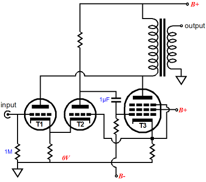
I was refering to this schematic posted by Globulator:
Waitadarnminute... I'm just noticing official AX Octode doesn't even use
the grounded grid, cathode to cathode coupling. Operation as described
in great length and detail in the article. But instead each cathode drives
a grid of the opposing side's driver...
No wonder sims based pon theory of operation in AX article don't work well.
The actual working Octode amp is completely different! Dude writes a whole
article of plausible science fiction, then neglects to follow his own imaginary
rules... Go figure!
If the addendum schematic is correct...
But if the schematic from 1/10 works, then I might be interested in building it anyway, first all tube, then with CCS and MOSFET output or change to 6V6s for the output triode/pentode to get 10W. Two 20M90S transistors in parallel should work well for the CCS at 40mA with plenty of protection for the large voltage swing. Is there any advantage to using the Triode Trick from Bill Perkins for strapping the pentode into triode?
I think the OPTs were supposed to be 8200R primary too.
I have the AX schematic sim up and working correctly.
Excepting for my OPT impedance is still 5KPP, I havn't
got round to figuring Henry ratios for AX Octode OPT?
The triode in that one does actual work into the load.
There is class A current swing, and the loadline won't
be dead flat Mu because of it, but it does add power.
---------
Broskie variant with current feedback resistor. Isn't
gonna be pure current mode output, there is still a
voltage feedback into the triode's plate. In lala land
somewhere between current and voltage. Damping
factor can be adjusted up and down that cathode
resistor. Perhaps if Broskie had imagined it as a pot?
Last edited:
"Here is the schematic:......"
"Huh!! Sure you've got the right schematic? Thats not even remotely similar to what we've been discussing!"
"Waitadarnminute... I'm just noticing official AX Octode doesn't even use
the grounded grid, cathode to cathode coupling. Operation as described
in great length and detail in the article. But instead each cathode drives
a grid of the opposing side's driver..."
We've been bait and switched I think. But the Yundt type design they ended up with is an excellent one. With lots of interesting variations possible. How about triode/anti-triode for the Class A part. Pentodes as is or Mosfets directly to the secondary for the Class AB part. Now we can have an effective Class AB triode/anti-triode SE emulation. Hmm, well not so straightforward I guess, need some way to sample the Class A currents. Well, if the Mosfets drive the secondary, then the primary side could be split at the B+ terminal for current sense resistors, still not real convenient. Could get the current sense R's down to ground level with two separate B+'s for the triode/anti-T sides. Some more thinking required, has to be a more convenient way.
Last edited:
Triode/ anti-Triode extension
Per the above mentioned scheme. Triode and anti-triode for the Class A portion, and Pentode/Mosfets for the Class aB portion.
OK, I think I see a way now. Instead of using the usual Mosfet for the anti-T side, use an identical triode there (T and "anti-T" still setting on a CCS tail per the usual anti T scheme).
Normally we use a Mosfet for the anti-triode side to get the high gm required for complementary current. But an alternative is to use a side diffl. ampl. (SDB) which controls the anti-triode's grid in such a way that the CCS tail stays near constant voltage. Then current sense resistors --could-- be put in both cathode sides to get the control current signals. Then the V5, V6 stage of the final Octode schematic to get the Pentode/Mosfet drives.
But maybe an easier way (well after a few manipulations). Just pick off the SDB drive voltage for the anti-T grid and use that for one (side B) pentode/Mosfet drive too. (likely have to put a series resistor in the anti-T's cathode to get current sensing inherently) (the SDB output would use an attenuator to the "anti-triode" grid, but direct connect to the pentode/Mosfet grid, only half of this signal then gets used by the pentode/Mosfet due to it's class B biasing)
We could then put another gain stage in (SDA, like V5,V6 in the final Octode schematic) for the triode side current sense, generating the (side A) Pentode/Mosfet drive. But with the two power Pentode/Mosfet sides running Class B, we might be able to recombine the two diffl. ampls. (SDB and SDA) into one diffl amp. again (since it is time shareable). So a bit of reconfiguring of V5,V6 in the final Octode schematic might get a Triode/anti-T mode Class A section plus pentode/Mosfet drives for Class aB.
More detail work needed of course.
Last edited:
Hmmm, on second thought, thats not going to work to timeshare the V5,V6 diffl. ampl., because the Class A part is always needed. Back to the drawing board.
The anti-triode is a special case of a current booster with a gain of (-1)
I wonder about a Class A + Class B stage like this what happens wrt OPT leakage inductance when either of the class B elements stops conducting.
I wonder about a Class A + Class B stage like this what happens wrt OPT leakage inductance when either of the class B elements stops conducting.
The anti-triode is a special case of a current booster with a gain of (-1)
I wonder about a Class A + Class B stage like this what happens wrt OPT leakage inductance when either of the class B elements stops conducting.
They don't stop abruptly, they stop gradually decreasing current while current through class A stage increases.
Here was my version (bottom transistors should be PNP, it was drawn in a hurry).
However, it is not a tube amp, but the principle is similar, and emitter currents of class C transistors decrease gradually, while voltage drop on R1 gradually goes down, and base current ceases.
The main difference is, I didn't sense current through class C devices for feedback. I arranged nested feedbacks such a way so transfer functions of class A stage including R1 in mind and of class C stage continue each other smoothly. The amp was built as drawn in late 1970'th for bass guitar, but sounded surprisingly well for Hi-fi, much better than conventional then "well biased" class AB amps. Actually, it sounded kind of "tubey".

"Here is the schematic:......"
"Huh!! Sure you've got the right schematic? Thats not even remotely similar to what we've been discussing!"
"Waitadarnminute... I'm just noticing official AX Octode doesn't even use
the grounded grid, cathode to cathode coupling. Operation as described
in great length and detail in the article. But instead each cathode drives
a grid of the opposing side's driver..."
We've been bait and switched I think. But the Yundt type design they ended up with is an excellent one. With lots of interesting variations possible. How about triode/anti-triode for the Class A part. Pentodes as is or Mosfets directly to the secondary for the Class AB part. Now we can have an effective Class AB triode/anti-triode SE emulation. Hmm, well not so straightforward I guess, need some way to sample the Class A currents. Well, if the Mosfets drive the secondary, then the primary side could be split at the B+ terminal for current sense resistors, still not real convenient. Could get the current sense R's down to ground level with two separate B+'s for the triode/anti-T sides. Some more thinking required, has to be a more convenient way.
Seems to be the consensus now and JRB figured out that all tube doesn't work so well if you follow the article's description. What's interesting is JRB also discussed combination amps some time ago, but years after Yundt's paper was published. I have to admit, I haven't had time to read it yet, but I did save it so I can read it later.
I'm a mechanical, hands-ons type, so digesting so much theory gives me head aches in short order. I do want to learn the theories, it just takes a long time for it to sink in and be applicable for me to mod other existing designs. I get the urge to yell, "just tell me how to do it, and let me build it already!" Not to the extent of Ready, Fire, Aim; but my trigger finger is pretty itchy right now.
So, are the characteristics of EL34s and 6L6s close enough to 6V6GTs to get me in the ball park with that schematic using 6922s and 6V6s? The voltages are fine for the 6V6GTs. I won't push my NOS tubes there, but new construction JJs and a couple others for guitar amps hold up fine. I'd like to get the voltage down to 250V-270V though so I can use my precious MWT 6V6GTs without too much concern.
I need to understand all the comments on minimizing the 3rd order HD, as I love the P-P topology except for the fact that 3rd order passes right through or is amplified...
Another newbie question. If I'm using a separate 12.6Vdc regulated PS for the 6.3V heaters wired in series, do I still need the heater reference? My intent is to have the heater circuit completely separate and regulated DC. I'd need 2, since they are limited to 5A @ 12.6V, but I plan to keep the all the tubes on one channel on one supply. This also lets my use SS for the HV PS and bring t he heaters up separately prior to B+.
Something like 20 clean watts with 6V6???
I havn't calculated OPT impedance yet, but
I've fooled with 2ndary Henries till this sim
loads the plates about right.
Can someone explain why the resistor values
above and below the error correcting triodes
are so finniky. Change even a little bit, and
the whole sim locks up like a rock...
I havn't calculated OPT impedance yet, but
I've fooled with 2ndary Henries till this sim
loads the plates about right.
Can someone explain why the resistor values
above and below the error correcting triodes
are so finniky. Change even a little bit, and
the whole sim locks up like a rock...
Attachments
"Seems to be the consensus now and JRB figured out that all tube doesn't work so well if you follow the article's description. "
Well, maybe JRB hadn't seen the final schematic yet. I think what he was hinting at with the extra resistor from the unused triode grid to the pentode cathode may have been to get the pentode current matched (at some multiple to) the power triode current. The Yundt type of setup (final Octode schematic) where the triode currents are monitored and the pentodes just driven, does not guarantee that the pentode is accurately copying the triode. It only guarantees that the triode becomes unloaded, leading to lower triode distortion. With enough gain (V5,V6), it makes the power triode operate at constant current (and no contribution to the output power either).
Yundt was interested in vanishingly low distortion. But the Octode seems more oriented toward retaining the triode signature, while increasing it's power. This calls for a linear impedance converter circuit, not a Yundt circuit. JRB's mod was to obtain a linear impedance converter (triode and pentode currents linearly related. JRB has a blog on impedance converters too by the way). We would do well to follow the same advice for making a class B assisted Triode/anti-triode setup, or any other "tubey" variants. Only problem is the # of Op Amps or diffl. stages to control the two pentodes and the anti-triode (3) is getting rather out of hand. The final Octode design may have reverted to the Yundt type design simply by default, just to get rid of the second diffl. stage, although they never indicated the crucial monitoring of pentode currents in the article to begin with. Our job, should you chose to accept the mission, is to figure out how to do two linear impedance converters (and maybe the anti-T control too) without so many tubes for all those "Op Amps".
http://www.tubecad.com/2009/09/blog0171.htm
Last edited:
"6DJ8 Triodlington with MOSFET...
Why make it complicated? "
True enough. I was thinking of the P-P emulation mode for SE. Triodelington will need an inductor for pullup. Unless you've got some kind of anti-triodelington to go with it.
Why make it complicated? "
True enough. I was thinking of the P-P emulation mode for SE. Triodelington will need an inductor for pullup. Unless you've got some kind of anti-triodelington to go with it.
6v6 sim is a little more forgiving if the error amplifying LTP is split in two tails
with either a capacitor or small value resistor spanned between. I'm not sure
why the maths of split tail any easier for LTSpice to digest than a single tail?
with either a capacitor or small value resistor spanned between. I'm not sure
why the maths of split tail any easier for LTSpice to digest than a single tail?
"They don't stop abruptly, they stop gradually decreasing current while current through class A stage increases."
Interesting point. If one did make separate strictly linear impedance converters (separate Op Amp controls for each) to control two class B outputs from a class A model stage, there could be a crossover transition issue if not handled carefully. The single OP Amp control smoothes the transition more easily.
"Unless you've got some kind of anti-triodelington to go with it."
A triodelington or similar with a CCS tail over to a Mosfet (per usual anti-T scheme) should work for a class A P-P output, but we don't seem to have a good class B solution without a bunch of Op. Amp. controllers. A least the impedance converter approach gives some starting point to try to simplify down.
Maybe the tube parts of two triodelingtons could be CCS tail coupled somehow (class A), with the Mosfet part sources connected to ground for class B operation. Then force one tube into anti-T mode.
Like say Sziklai/CFP style triodelingtons with the tube sections in CCS tail configuration (class A), but the Mosfet parts grounded source (and class B biased). Then a single Op Amp control or diffl control stage to get one triode to operate in anti-T mode. Or just use a Mosfet for the anti-T tube to start with. Makes for some grounding issue to drive the triode then since the new ground is at the plate potential (CFP Mosfet source actually). Well the output Mosfets could just use a separate LV supply with a different ground (the sources) for their biasing, gates AC coupled from the "tube" plates if necessary . Then the triode can operate normally. Seems workable. Have to check details.
Last edited:
Triode/Anti-triode with class B impedance conv. boosters
Details, details:
Easy to do I think. Just use a straightforward triode and anti-T (Mosfet) on a CCS tail per usual setup. Then Mosfet or emitter followers off the plate/drain of the T/anti-T driving a low Z OT (power toroid maybe).
A separate LV supply for the followers. They get biased to Op in class aB.
Next challenge, to get rid of the OT too.
- Home
- Amplifiers
- Tubes / Valves
- van Dorn's Octode design - recommendations for a 10W/ch version