Details, details:
Easy to do I think. Just use a straightforward triode and anti-T (Mosfet) on a CCS tail per usual setup. Then Mosfet or emitter followers off the plate/drain of the T/anti-T driving a low Z OT (power toroid maybe).
A separate LV supply for the followers. They get biased to Op in class aB.
Next challenge, to get rid of the OT too.
😱 Now you want to get rid of the iron too? Might as well just move this to the SS forum and I'll go build my F5 clone. 😛
Details, details:
Easy to do I think. Just use a straightforward triode and anti-T (Mosfet) on a CCS tail per usual setup. Then Mosfet or emitter followers off the plate/drain of the T/anti-T driving a low Z OT (power toroid maybe).
A separate LV supply for the followers. They get biased to Op in class aB.
Next challenge, to get rid of the OT too.
Bonus points for incorporating Schade feedback and lots of crossed wires?
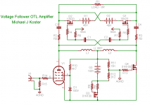
Here's another sketch out of my notebook I've been working on. It may have serious defects as it's only a work in progress...
The output reference and bias control is not shown. Not figured out actually.
Michael
Hmm.. operate the pentode in a linear current region and lose the shunt regulator...
Attachments
Last edited:
Except I don't see any "voltage follower"?
Just Pentode vs MOSFET LTP (Whichever one
dresses as whose Auntie? We don't know...)
No Mu, No Schade, No local NFB cept what
little might squeeze through gaps in screen
and/or Miller to Gate.
Just Pentode vs MOSFET LTP (Whichever one
dresses as whose Auntie? We don't know...)
No Mu, No Schade, No local NFB cept what
little might squeeze through gaps in screen
and/or Miller to Gate.
Last edited:
Umm, OTL Schaded Mosfet Circlotron. Nice way to get complementary drivers back to a psuedo SE output without an OT. 9 out of 10 bonus points. (Had to take a half pt. off for the missing Schade or screen feedback on the pentode per Ken, and another half point off for that pesky dual inductor plus dual floating B+ supplies. ) Not bad at all. It'll be tough to top that approach.
Only other way I see would be to use a totem pole anti-T scheme in class A with some complementary SS followers in class B. Not as clean an anti-T though unless some floating Op Amp stuck in. And the complementary followers may be a bit unmatched. Would eliminate the floating B+ supplies though.
Hmm, or just go real SE OTL mode and use a switched ferrite inductor for the pullup current. For this switched inductor thingy, I think it just takes two opposite windings on it and two Mosfets switched on/off complemntary wise. (this turns the audio signal into HF for the ferrite inductor) If the inductor is sized correctly, the Mosfets can run 50/50 duty, so no HF (well, no fundamental HF, still a bit of commutating SHF glitch, a few turns on a ferrite rod maybe to fillter that) to filter.
Last edited:
OK, reeling you guys back in...
Using the van Doorn modded Yundt schematic Fig, 1 I posted on page 1 of the thread, smoking-amp and Ken mention replacing R14 with a CCS. This is feeding the 6922s and they will be in Class A, so it should work, correct? Will Bill's triode trick with the zenner/C/R strings work to strap 6V6s into triode for the Class A portion of the output? I'd use 6V6s for the pentodes too, so which R or C values are critical in the schematic to it's performance and may need adjusting for the best crossover? To keep my NOS tubes safe, I may drop the voltage down to 225V for the B+.
I have purchased JRB's P-P output software, but I haven't used it yet and I'm assuming I could put this P-P topology into the the sw for sim, but the crossed parallel connections at the OPT are what have me confused.
And finally, if it does appear to work for the the CCS at R14, what transistors would you use?
In the future, I'd love to build a 40W-70W hybrid version with paralleled Toshibas MOSFETs for the outputs with no OPT being fed by the 6922 and one 6V6 in triode, but for now I want to focus on building an all 6V6 version of the Octode.
(sound of fishing reel reeling in the line)
On the CCS thing, I think we were not seeing (maybe JB too) the original intention of the circuit. We were interpreting it as a Terman type inverted triode feedback thru the 1st triode. With a second triode/ LTP incorporated to provide loop gain. For that mode, the 1st triode would be a small one, matched to the second LTP triode, and a CCS tail would make good sense for linearity and gain.
Seems what van Dorn actually intended though was for the 1st triode to be a power triode with a small current sensing resistor in the cathode. The small current sample signal then gets multiplied up by the second triode (in grounded grid mode there originally) to drive the pentode grid. (JB then indicated his mod to get the pentode current, rather than it's grid drive, proportional to the power triode current) When van Dorn went to a full P-P schematic, he apparently found it economical to change the gain stage configuration (grid input instead of cathode input) so that both P-P sides could be combined in the single V5,V6 LTP amplifier. (this eliminates the possibility for doing JBs mod though, which would take two LTP gain stages still) (probably why JB never followed up on the thing)
So the only change I would see for the R14 tail might be to rescale its value for the new 6V6 current level. Ie, if the 6V6 "triode" draws 1/2 the current of the EL34 "triode", you might want to double the resistor value to get the same current sense signal to amplify. However, if the 6V6 pentode has more gm than the 6L6 pentode did, then the signal does not need as much scaling up. So a couple of small compensation calcs to do, result: probably not much change in value to R14 required then. Then of course, DC biasing of grids to touch up, but that may well be in the range of the original design.
But then, if you are intending to go with JBs mod, you mainly just have to choose a current sense resistor for the pentode cathode that will give the required ratio of currents between the two devices. (with respect to the R14 "triode" sense resistor, ie, for 4X pentode/triode current, 1/4 the Ohms of R14 for the pentode cathode resistor) Then something needs to be worked out to get the DC grid voltages matched up so the LTP triodes are current balanced at idle.
And if you want to go with the Terman type inverted feedback scheme, then the "triodes" would want to be matched, could be smaller than 6V6, and the tail resistor could be either much higher Ohms to a B-, or a CCS circuit, set to some suitable current level for the triodes. JBs mod can then be incorporated too, but will just raise the output Z of the whole thing.
Last edited:
(sound of fishing reel reeling in the line)
On the CCS thing, I think we were not seeing (maybe JB too) the original intention of the circuit. We were interpreting it as a Terman type inverted triode feedback thru the 1st triode. With a second triode/ LTP incorporated to provide loop gain. For that mode, the 1st triode would be a small one, matched to the second LTP triode, and a CCS tail would make good sense for linearity and gain.
Seems what van Dorn actually intended though was for the 1st triode to be a power triode with a small current sensing resistor in the cathode. The small current sample signal then gets multiplied up by the second triode (in grounded grid mode there originally) to drive the pentode grid. (JB then indicated his mod to get the pentode current, rather than it's grid drive, proportional to the power triode current) When van Dorn went to a full P-P schematic, he apparently found it economical to change the gain stage configuration (grid input instead of cathode input) so that both P-P sides could be combined in the single V5,V6 LTP amplifier. (this eliminates the possibility for doing JBs mod though, which would take two LTP gain stages still) (probably why JB never followed up on the thing)
So the only change I would see for the R14 tail might be to rescale its value for the new 6V6 current level. Ie, if the 6V6 "triode" draws 1/2 the current of the EL34 "triode", you might want to double the resistor value to get the same current sense signal to amplify. However, if the 6V6 pentode has more gm than the 6L6 pentode did, then the signal does not need as much scaling up. So a couple of small compensation calcs to do, result: probably not much change in value to R14 required then. Then of course, DC biasing of grids to touch up, but that may well be in the range of the original design.
But then, if you are intending to go with JBs mod, you mainly just have to choose a current sense resistor for the pentode cathode that will give the required ratio of currents between the two devices. (with respect to the R14 "triode" sense resistor, ie, for 4X pentode/triode current, 1/4 the Ohms of R14 for the pentode cathode resistor) Then something needs to be worked out to get the DC grid voltages matched up so the LTP triodes are current balanced at idle.
And if you want to go with the Terman type inverted feedback scheme, then the "triodes" would want to be matched, could be smaller than 6V6, and the tail resistor could be either much higher Ohms to a B-, or a CCS circuit, set to some suitable current level for the triodes. JBs mod can then be incorporated too, but will just raise the output Z of the whole thing.
Man, that's a keeper!
Thanks s-a. At this point I do plan to build to the schematic, all 6922s will be 6n23Pi and the 6L6/EL34s replaced with 6V6s to be compatible with my 10W OPTs. I just have to figure out what values to tweak in the zenner string for strapping the 6V6s or see if it sims.
One more question that was just triggered, WRT to the article versus actual schematic. The whole reason I really started pursuing this 10W version is because my existing OPT iron is 8200R CT : 8R which is the primary impedance discussed in the article to properly load the triode and the pentode. But now that it has become clear the article doesn't relate to the actual schematic, will the 8200R cause a problem? If it just knocks down power, that's actually a good thing since I could potentially be overloading the OPTs by 2-3W if the power of all the 6V6s was at their maximum and truly sums.
Correction:
I didn't check the schematic when I last commented. It's not R14 that might need changing, but R8,R9. These are the current sense resistors for the "triodes".
Probably don't need much change, but I still would check according to triode current before and after a tube type change. The 6922 I assume is staying the same.
Using the P-P schematic, there is no provision to use JB's mod for Pent. current monitoring. That would require splitting the V5,V6 LTP into two LTPs. R21 and R26 are the pentode cathode current sense resistor positions, but are being used to linearize the pentode V to I (current) response some (not much) now, but seem to be typical value I sense resistors. (later schematic, maybe they were put in for safety reasons, fuses)
Or could go back to two of the earlier schematics.
Last edited:
Thanks. Correct, I'm keeping the 6922s and specifically using the 6n23Pi now, but may roll in 6H30s later. The 6V6 tubes will be either GE 6V6GTAs or MWT 6V6GTs. I have enough to use either brand or a combo of both so I'll see if there is significant differences between all GE, all MWT, or swapping one set of each for the triode or pentodes. If I do hear significant enough differences, then I'll chase down some Coke bottle 6V6Gs (which is also why I'll drop the voltage a bit to 225V).
I'll use separate regulated DC heater supplies and probably use Broskie's tube/sand rectifier PS boards so I can use SS now, then experiment with tube rectifiers later if I come across vintage iron that will work to minimize additional costs.
I'll use separate regulated DC heater supplies and probably use Broskie's tube/sand rectifier PS boards so I can use SS now, then experiment with tube rectifiers later if I come across vintage iron that will work to minimize additional costs.
Last edited:
Did you notlook the .asc file I sent regarding 6V6? I had all the bias worked out.
There was just this annoyance with LTSpice locking up on 1ohm change either
way. Somehow I don't think would happen in reality...
The 6V6 Triodes were biased at 30mA (11.5W per plate) and swung +-25mA Class A1.
The 6V6 Pentodes were biased at 20mA (7.5W per plate) swing +130/-20mA Class AB1.
To the tune of about 20W clean 1K sinewave into 8ohms.
There might be a few more peak watts lurking in A2, but the crossing becomes messy
if you operate at excessive volume continuously (Bias pumps itself toward cutoff) ...
Last edited:
Did you notlook the .asc file I sent regarding 6V6? I had all the bias worked out.
There was just this annoyance with LTSpice locking up on 1ohm change either
way. Somehow I don't think would happen in reality...
The 6V6 Triodes were biased at 30mA (11.5W per plate) and swung +-25mA Class A1.
The 6V6 Pentodes were biased at 20mA (7.5W per plate) swing +130/-20mA Class AB1.
To the tune of about 20W clean 1K sinewave into 8ohms.
There might be a few more peak watts lurking in A2, but the crossing becomes messy
if you operate at excessive volume continuously (Bias pumps itself toward cutoff) ...
I only saw .txt files and wasn't sure what to do with them as I don't have LTSpice loaded on this PC. What voltage did you use for B+ in the sim or does it matter? I can't tell if it was 350V or 275V in the txt file. Would those files import correctly to LTSPice if I install it?
Sorry, I'm a complete noob on the sim side, so it just went over my head, but I really appreciate your efforts.
I suspect 20W is a little excessive for my OPTs, but I doubt I will be driving them that hard 99.9999% of the time. It would be used for modded TB W8 FR drivers in the Decware Zen Open Baffle cabinets and my orthodynamic headphones which are 60R and would be hooked directly to the 8R taps via a 4-pin XLR.
Last edited:
Alarm Bells
I just realized that the final octode schematic is using the most non-linear portion of the power triode curve for control of the pentodes (turnoff to 1/2 on). This is due to the inversion in V5,V6 now (the earlier version did not have this issue), and the compensating inversion of the crossed pentode plates. The power triode and controlled pentode are not tracking current wise this way, but rather acting in class A/Class B P-P. This means that there is significant signal compression at large signal levels (where the controlling triodes are turning off), producing odd harmonics. Perhaps Ken's simulations would show this.
If that proves to be the case, I would recommend returning to the earlier Octode schematic, doubled up for P-P. Then you could try JB's mod too.
False Alarm!
I guess I wasn't quite awake yet so early. The V5,V6 LTP is controlled by BOTH triodes, so it's a Class A linearized P-P signal that is controlling the pentodes. I'm going back to sleep. Too early.
Changing R14 to a higher value off of a B- supply, or a CCS of the same current, might be helpful though for the above reason, to get both triode inputs equally weighted. With a low value R14 to ground, it does tend to emphasize the wrong input. (unless, possibly, that 1.8 K is tweaked for 3rd Harmonic suppression)
Last edited:
Thanks guys, I really appreciate all the help and the willingness to try to make this concept, or the extensions of this concept, work. You guys (both in this thread and the others in the forum) are the reason I'm a Fanatic Supporter and plan to bump it to full Sponsor when it's time to renew. I'm learning so much, even if it is a slow absorption process.

I'll be ordering my sockets, caps, and resistors shortly as I have two other small projects that also need parts. I'll be ordering PS iron from SumR for them too, so I'll tack this iron on to that order too.
Please feel free to keep the discussions of the other tweaks and concepts going in this thread, but know that I'm moving forward. I'll post questions here as they come up so others may find it later while using search functions. I suspect I'll have more questions for Ken once I get LTSpice loaded and try to recreate his work.
remove .txt from the end of my files.
Thats just cause this board doesn't yet recognize .ASC and .INC as valid file types.
And the contents ARE plain text readable, sorta....
Thats just cause this board doesn't yet recognize .ASC and .INC as valid file types.
And the contents ARE plain text readable, sorta....
I guess you ran out of LED symbols in the Simulator?? Makes a better "triode" curve for the Mosfet maybe?
I considered the Darlington output too, but it doesn't look so easy to make that into a triode/anti-T setup (using CCS tail). If you change U4 to something higher gm, then M2 doesn't get much gate drive signal. Maybe could fix that up by getting rid of the Schottkys on that side or a big cap across them.
I considered the Darlington output too, but it doesn't look so easy to make that into a triode/anti-T setup (using CCS tail). If you change U4 to something higher gm, then M2 doesn't get much gate drive signal. Maybe could fix that up by getting rid of the Schottkys on that side or a big cap across them.
Go ahead, ask me why all the Schottkys?
Because otherwise it would remind my Barracuda. 😀
Attachments
Cause MOSFET may technically be some kinda
square law device like 6L6? It isn't usefully so
AB crossing at wannabe tubelikeish currents.
Wasn't just cause I didn't have Spice model
for an LED or anything like that... There is
really something almost 6L6 magical about
how Schottky diode crossing curves mate...
Schottky diode stacks shape much cleaner AB
crossing here than MOSFETs by themselves.
---
Also the circuit was simplified by eliminating
the differential error amplifier. Each class A
triode controls only AB dumper on own side.
Each Triode's alternately has negligible current
influence when its dumper completely cuts off.
So makes a big difference the AB transition
smoothly hands over control of Mu from one
class A triode to the other.
Last edited:
- Home
- Amplifiers
- Tubes / Valves
- van Dorn's Octode design - recommendations for a 10W/ch version