![WP_20170727_001[1].jpg](/community/data/attachments/568/568168-b1ec502f321f0f203dd66a753fb4a333.jpg?hash=sexQLzIfDy)
Thanks Deux ex machina 🙂
So its 0.8V drop at 1A and two drops will be in a bridge i.e. 1.6V loss. Thus this 6.6V AC trafo drops below 5V AC given the 6.4VDC Merlin reported at his LM317s inputs when loaded. That is only good for non regulated DC or just AC heating. Even if using LM1117 (the adj variety) regs they are 1.2V min drop spec LDO at 800mA. No solution even with Schottky bridges. Only solution I see for sustaining two branches of regs with this trafo is a voltage doubler per winding.
Voltage doubler - Wikipedia
The KBU4 datasheet states a voltage drop of 1V @ 4A for the whole bridge, i.e. 0.5V per diode. Maybe, this isn't sufficient, though.
Btw, it is spelled deus... ;-)
Best regards!
Btw, it is spelled deus... ;-)
Best regards!
Fig2. Curve is for the whole bridge or per diode device? Anyway not sufficient in any case. Yes its Deus, I must install a spell checker. 🙂
Don't know either, as the Electrical Characteristics value doesn't correspond to the one that can be derived from the Fig. 2 curve.
Best regards!
Best regards!
Even if its 1V drop for the whole bridge we still face a roughly 5.25V AC loaded result per winding. Impossible to sustain any LDO fitting the 317 form factor and connectivity. I don't know, then there are only SMT LDOs made for digital stuff in mind which are very efficient but will need luck for heat dissipation at nearly 1A per branch. 1A is max for this TI one that has 0.3V min drop and could be set at 6V if the mains would be never below 230V and some guys offer it soldered on PCBs also: http://www.ti.com/lit/ds/symlink/tps7a47.pdf
Even the above scenario is right on edge borderline...
Even the above scenario is right on edge borderline...
The tx have two secondaries more of 5,2V AC 3 A each so can reach together 11,8V AC?
Salas I use for C4 0,047uF as interstage coupling capacitor, can be the reason of weak bass?
Salas I use for C4 0,047uF as interstage coupling capacitor, can be the reason of weak bass?
The tx have two secondaries more of 5,2V AC 3 A each so can reach together 11,8V AC?
That I thought of too but it would lose the separate heater branches advantage. The other branch can't be independently grounded anymore (watch that or it will short). It will receive the cathode voltage lift of the other branch but it could be a solution if no hum or SQ loss occurs.
Salas I use for C4 0,047uF as interstage coupling capacitor, can be the reason of weak bass?
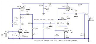
0.047uF is 47nF and its correct for flat. If it is not due to the cart VTA is bit wrong or some other TT setup detail is wrong then try R5 50K little higher first. Reference schematic is Rev 1.2 in post #1561.
Yes C4 is 0.1uF (100nF). C6 should also be no less than 2.2uF (as designated) for the bass alignment to remain correct enough. R8 820K can be made 1MEG to push the low bass a bit up if C6 is small and/or the following line preamp's Zin is below 20K.
C6 is 3,9uF
Salas attached schematic used for E283CC & 7N7 tubes.
Salas can't adjust to 6.1VDC because voltage of regulator jumps between 6VDC and 6.20VDC or more.
Salas attached schematic used for E283CC & 7N7 tubes.
That I thought of too but it would lose the separate heater branches advantage. The other branch can't be independently grounded anymore (watch that or it will short). It will receive the cathode voltage lift of the other branch but it could be a solution if no hum or SQ loss occurs.
Salas can't adjust to 6.1VDC because voltage of regulator jumps between 6VDC and 6.20VDC or more.
Attachments
Salas attached schematic used for E283CC & 7N7 tubes.
Make C4 0.1uF for more bass as in REV 1.2
Salas can't adjust to 6.1VDC because voltage of regulator jumps between 6VDC and 6.20VDC or more.
Measure if the regulator is dropping out. 317 needs at least 2.5V Vin > Vout.
Yes too hot but still can touch the heat sinks. Now solid as a rock 6,1VDC (when jumped I forgot to connect B+).
- Home
- Source & Line
- Analogue Source
- Valve Itch phono