If I remember well, freq = 1 means 1 times the sample rate, so for 1 kHz you would need freq = 1E3/(512*44100), and ampl = 0.5 corresponds to driving the percentage of ones between 25 % and 75 % (maximum Scarlet Book compliant level).
Code:
dout: -1 stffilt:  1.37806290399488668837E-0012
 sdout: -1 stffilt:  1.37806290399488668837E-0012
 sdout: -1 stffilt:  1.37806290399488668837E-0012
 sdout: -1 stffilt:  1.37806290399488668837E-0012
 sdout: -1 stffilt:  1.37806290399488668837E-0012
 sdout: -1 stffilt:  1.37806290399488668837E-0012
 sdout: -1 stffilt:  1.37806290399488668837E-0012
Just a little confused - we're using floating point but it's a bitstream. sdout = +1 or -1 for the bit value for each sample (ie 1 or 0).
Just seen your comment above - will try that.
Code:
93 -1,
94 -1,
95 -1,
96 -1,
97 -1,
98 -1,
99 -1,
100 -1,
101 -1,
102 -1,
103 -1,
I've used a teller then sdout[teller] to make an LTSpice file (it requires time then value), So for this I suspect I need to multiple by the sample index by the time period (ie ns)? For example:
Code:
1.217935141E-02 1,
 1.222363953E-02 1,
 1.226792857E-02 1,
 1.231221668E-02 1,
 1.235650573E-02 1,
 1.240079384E-02 1,
 1.244508289E-02 1,
 1.248937100E-02 1,
 1.253366005E-02 1,
 1.257794816E-02 1,
Last edited:
Yes, but please skip the first few thousand samples because of settling. LTSpice expects seconds rather than nanoseconds; for DSD512, the sample period should be 1/(44100*512) seconds. You can increase the constant lengte if the output file is too short for your purpose.
The original purpose of the program, at least of this version https://www.diyaudio.com/forums/dig...-sigma-delta-dac-operation-3.html#post5189375 , was to compare a sigma-delta modulator with a decimation filter against a linear filter with the same signal transfer followed by the same kind of decimation filter. That was needed to test Svitjod's hypothesis. I used rather basic filters to keep the program simple.
The program spits out a sigma-delta modulate and the linear filter's output signal into SDMout.txt, the floating point numbers come out of the linear filter you don't need. Low-pass filtered and decimated versions of both go into decimout.txt.
QQ on a separate subject, did you try TTL isolators? 150mbs, could run all the clocks and signal through then, rather than using a capacitor. It would perhaps remove the requirement to slow start the supply rails.
https://uk.rs-online.com/mobile/p/digital-isolator-ics/7098385/
https://uk.rs-online.com/mobile/p/digital-isolator-ics/7098385/
No I didn't, but judging by the datasheet, they should be a feasible alternative. You will probably have to find another way to make the -132 V and -137 V, because the current drawn by the isolators will be greater than what is drawn by the 74AHCT74s now.
I don't think the requirement to slow start the -300 V supply is a big problem, though. A simple CRCRC filtered supply like I use slow starts and slow stops automatically, as does anything with a series regulator with low-pass filtered reference and as do most switched-mode supplies.
I don't think the requirement to slow start the -300 V supply is a big problem, though. A simple CRCRC filtered supply like I use slow starts and slow stops automatically, as does anything with a series regulator with low-pass filtered reference and as do most switched-mode supplies.
Last edited:
Annoyingly I've hit a 32bit limit with free pascal attempting to create a larger sine wave - tried manually installing gnu pascal (no longer works as it's unsupported) and free pascal works right to this point but there's no way to pass the memory size model (it uses gnu) into the backend. I'll give it a rest for a couple of days. I think I'll transcode to C/linux and post it up for anyone to use.
I had looked at octave but it's floating point format max is a double or use vpa (variable number of digits - pretty much as many as you want but at a performance cost). Extended isn't supported as it's not standardised enough.
As I don't need to worry about the issues todo with long double or extended for this, it should work just fine.
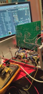
I left the first run going and then stopped it at 320mS. It's behaving nicely and looks to be about 2-5 seconds for the stabilisation of the biases to give a converged output.
I had looked at octave but it's floating point format max is a double or use vpa (variable number of digits - pretty much as many as you want but at a performance cost). Extended isn't supported as it's not standardised enough.
As I don't need to worry about the issues todo with long double or extended for this, it should work just fine.
I left the first run going and then stopped it at 320mS. It's behaving nicely and looks to be about 2-5 seconds for the stabilisation of the biases to give a converged output.
Frankly I'm amazed you can run such long LTSpice simulations in just a few days. 320 ms at 512 * 44.1 kHz is 7225344 clock cycles. I'm used to having to use workarounds for anything that settles really slowly, like DC blocking capacitors or DC loops, then simulating 25 000 cycles or so in an overnight Spectre APS run and using the last 16384 for the DFT. It's often with parasitic capacitance extraction, though, which makes the netlists rather long.
Frankly I'm amazed you can run such long LTSpice simulations in just a few days. 320 ms at 512 * 44.1 kHz is 7225344 clock cycles. I'm used to having to use workarounds for anything that settles really slowly, like DC blocking capacitors or DC loops, then simulating 25 000 cycles or so in an overnight Spectre APS run and using the last 16384 for the DFT. It's often with parasitic capacitance extraction, though, which makes the netlists rather long.
Mac Mini 2018, i7 6core (12 if you could hyperthreading), 32GB ram and SSD 😀 manages 3uS per second with ~60% cpu load for that 6SN7 dac model, the rate doesn’t change even when running an 8GB Linux VM and Xcode simultaneously. But if a beast in a small package.
I did find that LTSpice works best if you don’t have any plots displayed and let it just run in the background. I also keep in mind that the have default parameters that are designed for assisting convergence.
Moving forward I’ll do a run and use save bias to save the stable DC model, then use loadbias to kick start the tests with applied signals.
Simple C++ version of your Pascal.
Pascal allows some practices such as defining variables and assigning them in the parameters to function calls etc, not supported in C++.
You'll note a couple of things:
* use of random distribution rather than rand() as rand() gives an integer and using rand() mod range results in a biased random number. Instead using the random distribution and returning a random number 0-1.0 then multiplying is better and gives an even spread.
* use if string stream to allow the file output for long double used in place of pascal's extended. C/C++ optimises quite too readily to integers so you need 1.0 instead of 1 for example and ensure the casting maintains floating point.
Works - the settings it's on at the moment outputs a 1.11GB DSD512 file. I've not got LTSpice to load that yet.. so it may be beyond LTSpice. What I may need todo is simply create one cycle then use repeat forever if that works with PWL files. That way it should reuse the same data... The output still doesn't look right (ignoring the -1 with I will replace with 0).
Code:
//
//  main.cpp
//  dsdsignalgenerator
//


#include <iostream>
#include <fstream>
#include <sstream>
#include <cmath>
#include <random>

using namespace std;

//* Sigma-delta modulator with embedded pulse width modulator-like *)
//* thing with randomly rotated pattern. *)
//* Combined with very simple interpolation and decimation: *)
//* linear interpolation and sixth-order CIC decimation filter. *)
//* For comparison, also includes a linear time-variant filter *)
//* with equal signal transfer, but no quantization or PWM. *)

const long double freq = 1.0E3/(512.0*44100.0);
const long double sampleTime = 1.0/(512.0*44100.0);
const uint64_t lengte = 1*512*44100;
const uint64_t PBMlengte = 100;
const uint64_t CICorde = 6;
const uint64_t oversampling = 512;
const long double ampl = 0.5;


//(* maxn is the largest absolute value that the CIC registers can contain, *)
//(* it must be greater than the maximal CIC filter output signal before *)
//(* the correction for CIC filter gain, that is, greater than the maximal *)
//(* absolute value of state variable Mies[CICorde]. *)
long double maxn = round(exp(log((long double)oversampling)*(long double)CICorde)) + 1.0;

//(* Coefficients for procedures sigmadelta and stf, made global so *)
//(* consistency between the coefficients of these procedures is ensured. *)
const long double c1 = 0.004766840354*PBMlengte/2.0;
const long double c2 = 0.052844429735*PBMlengte/2.0;
const long double c3 = 0.256703167298*PBMlengte/2.0;
const long double c4 = 0.746792470683*PBMlengte/2.0;
const long double c5 = 1.255604698776*PBMlengte/2.0;
const long double i1 = 1;
const long double i2 = 1;
const long double i3 = 1;
const long double i4 = 1;
const long double i5 = 1;
const long double d1 = 0.0005;
const long double d2 = 0.004938272;

const long double pi = 4.0*atan((long double)1.0);


typedef long double Signal;
typedef int32_t IntegerSignal;
typedef long double CICstate; // 1 start - note for loops <=CICorde

long double xin;
long double xin_old;
long double xin_new;
long double filteredxin;
long double filteredsdout;

//(* int1 to int5: integrator states of sigmadelta, rotatie: variable *)
//(* of its rotating algorithm, kwant: latest quantizer value. *)
Signal *int1 = new Signal[lengte+1]; // 0 start;
Signal *int2 = new Signal[lengte+1]; // 0 start;;
Signal *int3 = new Signal[lengte+1]; // 0 start;;
Signal *int4 = new Signal[lengte+1]; // 0 start;;
Signal *int5 = new Signal[lengte+1]; // 0 start;;
uint64_t rotatie;
uint64_t vastgelopen; // tracks the number of quantizer clipping events
int64_t kwant;

//(* intnq1 to intnq5: integrator states of procedure stf, the linear *)
//(* time-variant filter that matches the sigma-delta modulator's *)
//(* signal transfer function. *)
Signal *intnq1 = new Signal[lengte+1]; // 0 start;;
Signal *intnq2 = new Signal[lengte+1]; // 0 start;;
Signal *intnq3 = new Signal[lengte+1]; // 0 start;;
Signal *intnq4 = new Signal[lengte+1]; // 0 start;;
Signal *intnq5 = new Signal[lengte+1]; // 0 start;;
long double nokwant;

IntegerSignal *sdout = new IntegerSignal[lengte];; // output signal sigma-delta
Signal *stffilt = new Signal[lengte+1]; // 0 start;; // output signal stf
uint64_t teller; // counter

//(* State variables of the CIC filters: *)
CICstate *aap = new CICstate[CICorde+1];
CICstate *noot = new CICstate[CICorde+1];
CICstate *Mies = new CICstate[CICorde+1];
CICstate *Wim = new CICstate[CICorde+1];
CICstate *Zus = new CICstate[CICorde+1];
CICstate *Jet = new CICstate[CICorde+1];

ofstream f;
ofstream fsd;
ofstream fdecim;
std::default_random_engine generator;
std::uniform_real_distribution<long double> distribution(0.0,1.0);

void sigmadelta(long double xin, IntegerSignal *uit, uint64_t teller, Signal *int1,
                Signal *int2, Signal *int3, Signal *int4, Signal *int5, uint64_t *rotatie,
                int64_t *kwant, uint64_t *vastgelopen) {
    uint64_t hulp;
    if(teller%PBMlengte==1) {
        *kwant=round( int5[teller-1]+(distribution(generator))+(distribution(generator))-1.0+((long double)PBMlengte)/2.0 );
        //(* Quantizer with triangular PDF dither. *)
        if(*kwant<0) {
            *kwant=0;
            *vastgelopen=*vastgelopen+1;
        }

        if(*kwant>PBMlengte) {
            *kwant=PBMlengte;
            *vastgelopen=*vastgelopen+1;
        }
        *rotatie=round(distribution(generator)*(long double)PBMlengte);
        //(*random integer from 0 up to and including PBMlengte - 1 *)
    }

    hulp=(teller-1+*rotatie) % PBMlengte;
    if(hulp<*kwant){ uit[teller]=1; }else{ uit[teller]=-1; }

    int1[teller]=(xin-c1*uit[teller]-d1*int2[teller-1]+i1*int1[teller-1])/(long double)PBMlengte+(((long double)PBMlengte-1)/(long double)PBMlengte)*int1[teller-1];
    int2[teller]=(int1[teller-1]-c2*uit[teller]+i2*int2[teller-1])/(long double)PBMlengte+(((long double)PBMlengte-1)/(long double)PBMlengte)*int2[teller-1];
    int3[teller]=(int2[teller-1]-c3*uit[teller]-d2*int4[teller-1]+i3*int3[teller-1])/(long double)PBMlengte+(((long double)PBMlengte-1)/(long double)PBMlengte)*int3[teller-1];
    int4[teller]=(int3[teller-1]-c4*uit[teller]+i4*int4[teller-1])/(long double)PBMlengte+(((long double)PBMlengte-1)/(long double)PBMlengte)*int4[teller-1];
    int5[teller]=(int4[teller-1]-c5*uit[teller]+i5*int5[teller-1])/(long double)PBMlengte+(((long double)PBMlengte-1)/(long double)PBMlengte)*int5[teller-1];
} // procedure sigmadelta

void stf(long double xin, Signal *uit, uint64_t teller, Signal *int1, Signal* int2, Signal *int3, Signal *int4, Signal *int5, Signal *nokwant) {
    if(teller%PBMlengte==1) *nokwant=int5[teller-1];
    uit[teller]=2.0*((long double)*nokwant)/(long double)PBMlengte;
    int1[teller]=(xin-c1*uit[teller]-d1*int2[teller-1]+i1*int1[teller-1])/((long double)PBMlengte)+(((long double)PBMlengte-1.0)/(long double)PBMlengte)*int1[teller-1];
    int2[teller]=(int1[teller-1]-c2*uit[teller]+i2*int2[teller-1])/(long double)PBMlengte+(((long double)PBMlengte-1.0)/(long double)PBMlengte)*int2[teller-1];
    int3[teller]=(int2[teller-1]-c3*uit[teller]-d2*int4[teller-1]+i3*int3[teller-1])/(long double)PBMlengte+(((long double)PBMlengte-1.0)/(long double)PBMlengte)*int3[teller-1];
    int4[teller]=(int3[teller-1]-c4*uit[teller]+i4*int4[teller-1])/(long double)PBMlengte+(((long double)PBMlengte-1.0)/(long double)PBMlengte)*int4[teller-1];
    int5[teller]=(int4[teller-1]-c5*uit[teller]+i5*int5[teller-1])/(long double)PBMlengte+(((long double)PBMlengte-1.0)/(long double)PBMlengte)*int5[teller-1];
} // procedure stf

void CICfilter(const long double inp, long double *out, CICstate *aap, CICstate *noot, CICstate *Mies, uint64_t CICorde, const long double maxn, uint64_t teller, uint64_t oversampling) {
    uint64_t localcounter=0;
    //(* CIC decimating filter *)
    aap[1]=inp+aap[1];
    if( aap[1]>maxn) aap[1]=aap[1]-2.0*maxn; // Folding applied to keep the state variables from exploding,
    if(aap[1]<-maxn) aap[1]=aap[1]+2.0*maxn; // does not cause distortion as long as maxn > maximum output signal
    for(localcounter=2;localcounter<=CICorde;localcounter++) {
        aap[localcounter]=aap[localcounter]+aap[localcounter-1];
        if(aap[localcounter]>maxn) aap[localcounter]=aap[localcounter]-2.0*maxn;
        if(aap[localcounter]<-maxn) aap[localcounter]=aap[localcounter]+2.0*maxn;
    }
    if(teller%oversampling == 0){
        Mies[1]=aap[CICorde]-noot[1];
        if(Mies[1]>maxn) Mies[1]=Mies[1]-2.0*maxn;
        if(Mies[1]<-maxn) Mies[1]=Mies[1]+2.0*maxn;
        for(localcounter=2;localcounter<=CICorde;localcounter++){
            Mies[localcounter]=Mies[localcounter-1]-noot[localcounter];
            if(Mies[localcounter]>maxn) Mies[localcounter]=Mies[localcounter]-2.0*maxn;
            if(Mies[localcounter]<-maxn) Mies[localcounter]=Mies[localcounter]+2.0*maxn;
        }
        noot[1]=aap[CICorde];
        for(localcounter=2;localcounter<=CICorde;localcounter++) {
            noot[localcounter]=Mies[localcounter-1];
            *out=Mies[CICorde]/exp(log((long double)oversampling)*(long double)CICorde);
        }
    }
} // procedure CICfilter

int main(const int argc, const char *argv[]) { // main program

    fsd.open("SDMout.txt", ios::out | ios::trunc); //(* timestamp bitstream sample rate output  formatted for LTSice *)
    fdecim.open("decimout.txt", ios::out | ios::trunc); // (* 100 kHz decimated output *)

    int1[0]=0.0006779986543;
    int2[0]=0;
    int3[0]=0;
    int4[0]=0;
    int5[0]=0.00014553722;
    intnq1[0]=0;
    intnq2[0]=0;
    intnq3[0]=0;
    intnq4[0]=0;
    intnq5[0]=0;
    sdout[0]=0;
    for(teller=1; teller<=CICorde; teller++) {
        aap[teller]=0;
        noot[teller]=0;
        Mies[teller]=0;
        Wim[teller]=0;
        Zus[teller]=0;
        Jet[teller]=0;
    }
    vastgelopen=0;
    kwant=round(PBMlengte/2); // int doesn't need rounding.
    xin_new=0;
    xin_old=0;
    fdecim << " filteredxin, filteredsdout, filteredsdout-filteredxin" << endl;
    teller=1;

    // write first point of the PWL file
    fsd << "0 0," << endl;
    fsd << "0 " << sdout[teller] << "," << endl;

    stringstream ss;
    ss.precision(std::numeric_limits<long double>::digits10);
    ss << sampleTime;
    fsd << ss.str() << " " << sdout[teller] << "," <<endl;
    teller=2;

    while( teller <= lengte ) {

        xin= c1*ampl*sin(2.0*pi*freq*(long double)teller);

        //(* Linear interpolation between input samples. *)
        sigmadelta(xin, sdout, teller, int1, int2, int3, int4, int5, &rotatie, &kwant, &vastgelopen);
        stf(xin, stffilt, teller, intnq1, intnq2, intnq3, intnq4, intnq5, &nokwant);
        CICfilter(sdout[teller], &filteredsdout, aap, noot, Mies, CICorde, maxn, teller, oversampling);
        CICfilter(stffilt[teller], &filteredxin, Wim, Zus, Jet, CICorde, maxn, teller, oversampling);

        stringstream ss;
        ss.precision(std::numeric_limits<long double>::digits10);
        ss << ((long double)teller)*sampleTime;

        fsd << ss.str() << " " << sdout[teller-1] << "," << endl; // complete the previous bit
        fsd << ss.str() << " " << sdout[teller] << "," << endl; // add the new transition

        if(teller % oversampling== 0)  fdecim << filteredxin << ", "  << filteredsdout << ", " << filteredsdout-filteredxin << endl;
        teller++;
        if(teller%8192==0) fsd.flush(); // don't wait, write some to file so we can check it.
    }

    fsd.close();
    fdecim.close();
    return 0;
}
Last edited:
The output signal is not periodic, creating one cycle and repeating it will result in a weird spectrum. For example, if you have a 1 kHz signal, make a 1 ms file and repeat it, you make a periodic waveform with 1 kHz fundamental, so all spectral components will be at exact multiples of 1 kHz. You can't tell the difference between shaped quantization noise and harmonic distortion then.
You could repeat a much longer section so most of the shaped quantization noise ends up at frequencies that are not exact multiples of the signal frequency, but that probably still messes up the noise shaping to some extent. At least there is no window function that smooths the transition from one section to the next. It should work when you only use the repeated waveform for initial settling and only use samples from one section for the DFT (with Hann windowing for the DFT).
You could repeat a much longer section so most of the shaped quantization noise ends up at frequencies that are not exact multiples of the signal frequency, but that probably still messes up the noise shaping to some extent. At least there is no window function that smooths the transition from one section to the next. It should work when you only use the repeated waveform for initial settling and only use samples from one section for the DFT (with Hann windowing for the DFT).
The output signal is not periodic, creating one cycle and repeating it will result in a weird spectrum. For example, if you have a 1 kHz signal, make a 1 ms file and repeat it, you make a periodic waveform with 1 kHz fundamental, so all spectral components will be at exact multiples of 1 kHz. You can't tell the difference between shaped quantization noise and harmonic distortion then.
You could repeat a much longer section so most of the shaped quantization noise ends up at frequencies that are not exact multiples of the signal frequency, but that probably still messes up the noise shaping to some extent. At least there is no window function that smooths the transition from one section to the next. It should work when you only use the repeated waveform for initial settling and only use samples from one section for the DFT (with Hann windowing for the DFT).
Agreed - I'm trying to find a simpler way to plot this with the different parameters just so I can review the wave form. Octave is possibly the easiest way.
The position I want to get to is simply - create a full wave then use PWL REPEAT FOREVER (file=wave.txt) ENDREPEAT. I can adapt the code to simply output one sine cycle after a number of cycles by watching the sine function - this may be the easiest way rather than plotting.
I may have to drop down to DSD64 simply for the initial testing then worry about 512 later - I know 512 is working with an alternating bit pattern.
Either I don't understand you or you don't understand me or both.
What exactly do you want to plot, just the output of the program? I normally use Gnuplot to make plots like the ones you see here: https://www.diyaudio.com/forums/dig...itter-crystal-oscillator-285.html#post6373471 and here https://www.diyaudio.com/forums/dig...-sigma-delta-dac-operation-4.html#post5190900
The low-pass filtered output signals are also decimated, so the horizontal scale is compressed compared to the sigma-delta modulate. The sigma-delta modulate itself just switches somewhat irregularly between -1 (or 0) and +1 all the time.
I suspect it my lack of clarity - no need to do anything 🙂
I think it’s on me to work out a bitstream. However I think LTSpice is limited to a small file too small for DSD :/ even with using PWL file loops.
Given a cycle it should be possible to build up a series implemented in LTSpice that outputs the bit sequences. Even if that is coded into a model.
A clock signal can then cause the series to be evaluated and the bit sequence is the output.
Finished-Not working
Hi,
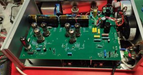
I have finished my built but, it is non-functioning.
I've got the following voltages:
B- : -287.3
D16 anode: -126.2V
D16 cathode: -131.9V
R111 to GND: 5.09V
All TPs:-122.1V
I get some sound but it is half speed (slow), noisy, and only from the positive node of the left channel.
P9, P11 shorted pins 1-2, and P8 shorted.
0 Ohm resistors on R59, R57, and R48.
Connected through BBGreen and PPY's ReClocker, fed though HQplayer 3 with DSD stream.
Since I have built everything for this project with all these SMDs and this is the first test for every part of the project, I do not know what is working and what is malfunctioning, so some help for debugging is what I am asking for because I've stacked.
Periklis
Hi,
I have finished my built but, it is non-functioning.
I've got the following voltages:
B- : -287.3
D16 anode: -126.2V
D16 cathode: -131.9V
R111 to GND: 5.09V
All TPs:-122.1V
I get some sound but it is half speed (slow), noisy, and only from the positive node of the left channel.
P9, P11 shorted pins 1-2, and P8 shorted.
0 Ohm resistors on R59, R57, and R48.
Connected through BBGreen and PPY's ReClocker, fed though HQplayer 3 with DSD stream.
Since I have built everything for this project with all these SMDs and this is the first test for every part of the project, I do not know what is working and what is malfunctioning, so some help for debugging is what I am asking for because I've stacked.
Periklis
An externally hosted image should be here but it was not working when we last tested it.
Hi Periklis hopefully you're not too far away and Marcel will be able to provide some insight.
Have you tested the BBB/reclocker on their own? Before I hooked up the Valve DAC I tried them with a simple low-pass filter no-dac to make sure I had a valid DSD signal.
Are all your potentiometers set to mid-travel - adjusting them on mine made a big difference to noise.
Ray
Have you tested the BBB/reclocker on their own? Before I hooked up the Valve DAC I tried them with a simple low-pass filter no-dac to make sure I had a valid DSD signal.
Are all your potentiometers set to mid-travel - adjusting them on mine made a big difference to noise.
Ray
Thanks Ray,
I'll try the BBB - Rclk first thing tomorrow morning, since I want to be sure about this is functioning properly.
I thought that since HQplayer is functioning, this part is ok, but maybe not.
On the initial test, one clock's voltage stabilizer was not soldered properly and I was not able to stream 44.1kHz multiples. When fixed HQplayer responded.
Periklis
Hi,
I have finished my built but, it is non-functioning.
I've got the following voltages:
B- : -287.3
D16 anode: -126.2V
D16 cathode: -131.9V
R111 to GND: 5.09V
All TPs:-122.1V
Supplies all close enough to the targets. Is the reference voltage about -202.3 V (85 V above B-)?
I get some sound but it is half speed (slow), noisy, and only from the positive node of the left channel.
Half speed can't be due to the DAC and only from the positive node must be due to the DAC, so you have at least two problems.
P9, P11 shorted pins 1-2, and P8 shorted.
0 Ohm resistors on R59, R57, and R48.
Correct settings for using the bit clock on the Amanero-style connector.
Connected through BBGreen and PPY's ReClocker, fed though HQplayer 3 with DSD stream.
Good, as with ppy's reclocker, the bug in the connections of the Amanero-style connector won't do any harm.
Since I have built everything for this project with all these SMDs and this is the first test for every part of the project, I do not know what is working and what is malfunctioning, so some help for debugging is what I am asking for because I've stacked.
Periklis
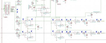
Could you check the DC voltages at the inputs of the DC blocking capacitors, so at the anodes of U1, U2, U28 and U30, while attempting to play music? They should all be somewhere around -28 V with respect to ground.
What voltages do you measure at the muteswitch nodes, that is, at the J109 gates? They should be around -15 V, although a typical digital multimeter with 1 Mohm input resistance will display about -7 V. If they are 0 V or slightly positive, the outputs are muted.
Besides, Ray's suggestion to do some experiments with a makeshift low-pass filter is a very good one. You can functionally check a raw DSD output with an RC low-pass filter at 20 kHz or so, for example 820 ohm and 10 nF or 2.2 kohm and 3.9 nF. Connect the DSD output to the filter, AC couple the filter's output to an amplifier with volume control using a coupling capacitor of a few microfarads, make sure not to turn up the volume too high and check if you have sound. The reason for not turning up the volume too high is that at high volumes, the remaining ultrasonic quantization noise might damage your tweeters or your amplifier.
You could disconnect the transformer windings used for the heaters and the -300 V, so the only supply you will have is the +5 V, and use such a low-pass filter to functionally test the DSD datapath all the way from the BeagleBone up to U12B/R37 and U13A/R38.
Hi Marcel,
Following your advice and Ray's I made the following measurements:
Rch
U28b, U30a : 0,034 VDC
U28a, U30b : -54,50 VDC
similar as if DSD signal was muted
Lch
U1b, U2a : -27,8 VDC
U1a, U2b : -26,43 VDC
correct, sound from Lch valid
J109 gates: -13.8 VDC
For results see attached image.
.......
Thanks for being so much helpfull with so simple and easy to follow suggestions. Of course, I understand that I have a long road to success, so if any more ideas come to you I would be glad to try.
Periklis
Following your advice and Ray's I made the following measurements:
Could you check the DC voltages at the inputs of the DC blocking capacitors, so at the anodes of U1, U2, U28 and U30, while attempting to play music? They should all be somewhere around -28 V with respect to ground.
Rch
U28b, U30a : 0,034 VDC
U28a, U30b : -54,50 VDC
similar as if DSD signal was muted
Lch
U1b, U2a : -27,8 VDC
U1a, U2b : -26,43 VDC
correct, sound from Lch valid
What voltages do you measure at the muteswitch nodes, that is, at the J109 gates? They should be around -15 V, although a typical digital multimeter with 1 Mohm input resistance will display about -7 V. If they are 0 V or slightly positive, the outputs are muted.
J109 gates: -13.8 VDC
low-pass filter at 20 kHz or so, for example 820 ohm and 10 nF
................
disconnect the transformer windings used for the heaters and the -300 V, so the only supply you will have is the +5 V, and use such a low-pass filter to functionally test the DSD datapath all the way from the BeagleBone up to U12B/R37 and U13A/R38.
For results see attached image.
.......
Thanks for being so much helpfull with so simple and easy to follow suggestions. Of course, I understand that I have a long road to success, so if any more ideas come to you I would be glad to try.
Periklis
Attachments
- Home
- Source & Line
- Digital Line Level
- Valve DAC from Linear Audio volume 13