Hi Ray, good luck with the remaining parts of the DSD-only valve DAC! I'm curious to know if it will work up to DSD512 without any tweaking of delay networks. My calculations say it should, but they don't take several second-order effects into account.
I also wonder if Dan managed to mount his huge capacitors and to get his version to produce sound. His last update was from just before Christmas.
I also wonder if Dan managed to mount his huge capacitors and to get his version to produce sound. His last update was from just before Christmas.
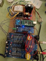
Some progres today, assembled and started testing the various power supplies.
Lower left is the Beaglebone Black (BBB) with its reclocker and power supply. I've had the BBB up and running and all seems fine.
Top left is a Neurochrome Maida regulator that will eventually provide the 300V B+. This tests out OK as per the build manual so ready to test with the full voltage at some point.
The other boards are simple regulators, one for the filaments and the other to power the reclocker and the LEDs I plan to put in the valve bases.
This remark is almost certainly unnecessary, but better safe than sorry: please keep in mind that the valve DAC needs a -300 V B- rather than a +300 V B+. That's just a matter of which side of the 300 V supply is connected to ground, but if the mounting holes on the 300 V regulator PCB make contact with what would normally be ground, they will in fact be at -300 V.
This remark is almost certainly unnecessary, but better safe than sorry: please keep in mind that the valve DAC needs a -300 V B- rather than a +300 V B+. That's just a matter of which side of the 300 V supply is connected to ground, but if the mounting holes on the 300 V regulator PCB make contact with what would normally be ground, they will in fact be at -300 V.
It's OK Marcel - I've got the negative 'B+' in mind and I've taken the precaution of mounting the HV regulator on plastic stand-offs. First thing though is to hook it up and check if I'm getting +300V DC out of it with a dummy load. That's complicated a little by my plan to eventually use the on board (on the DAC board) B- rectifier diodes and caps as the front end to the HV regulator - I have a seperate 'front end' I can use though.
Because of the way a PCB ground track is connected, I wonder if using the DAC board's diodes and capacitors is possible. See the three figures.
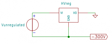
The first figure is a positive series regulator connected such that it produces a negative voltage. The unregulated source at the left has neither of its pins connected to ground. I assume this schematic also applies to your regulator.
The second figure shows a fragment of the valve DAC supply schematic (DSD only variant, but the same holds for the original). C122 has its positive pin grounded. When you reverse the diodes and electrolytics, it will have its negative pin grounded, but either way, it has a side connected to ground.
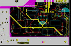
This wouldn't be a big deal if the connection could easily be removed, but it is actually a yellow track in the third figure, and yellow is an inner layer. Maybe you can still drill it out, but that will be tricky.
The first figure is a positive series regulator connected such that it produces a negative voltage. The unregulated source at the left has neither of its pins connected to ground. I assume this schematic also applies to your regulator.
The second figure shows a fragment of the valve DAC supply schematic (DSD only variant, but the same holds for the original). C122 has its positive pin grounded. When you reverse the diodes and electrolytics, it will have its negative pin grounded, but either way, it has a side connected to ground.
This wouldn't be a big deal if the connection could easily be removed, but it is actually a yellow track in the third figure, and yellow is an inner layer. Maybe you can still drill it out, but that will be tricky.
Attachments

Because of the way a PCB ground track is connected, I wonder if using the DAC board's diodes and capacitors is possible.
You're right of course Marcel - I didn't think that through very well

Fortunately I have plans B, C & D to fall back on...
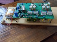
I made some solid progress today, installed more/updated power supplies and started to assemble the chassis. In the next day or two I hope to complete the installation of the power supplies and to test them.
For the 5V supply for the digital section I'm using a low noise TPS7A4700 module and for the B+ I have a self contained Maida regulator (with its own diodes/cap).

For the 5V supply for the digital section I'm using a low noise TPS7A4700 module and for the B+ I have a self contained Maida regulator (with its own diodes/cap).
It looks very nice! What's the size of the chassis?
Thanks Marcel. The chassis is one of these;
HiFi Aluminum Chassis DAC Metal Case Amplifier Enclosure DIY Audio Cabinet 7921734953154 | eBay
I had a free day today and made a bit more progress. I would have finished hooking up the power supplies and tested them all but I can't find the current limit resistor for the Maida regulator.

Thanks Felipe. 
I know I ordered the resistor and checked it off against the invoice but I've searched high and low... Anyway, I've got to place another parts order so will add one to that later today - that means the missing resistor will appear shortly afterwards.
The Maida reg will be configured to deliver 300V @ 50mA with the current limit set to 125mA.
Ray
Last edited:
I've been focussed on my SE-OTL projects of late - two flea power amps (one using 6h30pi and 13E1 tubes and the other 6SN7 and 6C33C tubes) to drive my Lowther horns that should complement this DAC project well. First one is now up and running so I'll put some more time into the DAC.
I received a package in the post today with another part of the jigsaw; 10uF 400V Arcotronics caps, good price on ebay.

I received a package in the post today with another part of the jigsaw; 10uF 400V Arcotronics caps, good price on ebay.
You need to learn how to rescale your pictures.
//
Thanks but I know how to do that should I choose.
Hi Ray / Marcel / Et al,
Apologies for my hiatus. I have been stuck elsewhere in the world with only a phone and work laptop and arrived back home last week.
Whilst self isolating for the next two - three weeks, with a mountain of post to get through and some uninvited visitors (the animal kind) I am aiming to get back on top of my projects some time this week or next.
Photos of DAC from beginning of Jan before I left show where I got to, along with a DSC1 board testing out the AK4137 conversion of PCM to DSD 256, which works, and will plumb into the Valve DAC board.
Photo's NOT resized so that detail can be reviewed in my shoddy soldering and scum encrusted PCB / Desk.
Having washed / scrubbed it in Isopropanol 2-3 times, how are you supposed to get flux off without leaving that layer of grease?
Attachments
I don't know, I never get it perfectly clean either. I just scratch off the big chunks when possible without damaging the solder mask, apply isopropyl alcohol with a cotton bud, try to remove it again with a dry cotton bud and hope for the best.
Last edited:
I use this stuff, does a really good job of removing the flux from my PCBs and various solder connections;
Servisol 6100019000 De-flux 160 Flux Remover 200ml | Rapid Online
Anyway, good to hear from you both.
Servisol 6100019000 De-flux 160 Flux Remover 200ml | Rapid Online
Anyway, good to hear from you both.
Last edited:
- Home
- Source & Line
- Digital Line Level
- Valve DAC from Linear Audio volume 13