I found an open link between R12 and V4 (238V) and a few minor errors now corrected.
Attachments

Here a potentiometer you can add to sch if you want, or just keyin "Pot" see it shows up.
If you want to model a SPDT switch read here: https://electronics.stackexchange.com/questions/372278/spdt-in-ltspice
I'll try to model when I'm free.
If you want to model a SPDT switch read here: https://electronics.stackexchange.com/questions/372278/spdt-in-ltspice
I'll try to model when I'm free.
Attachments
Last edited:
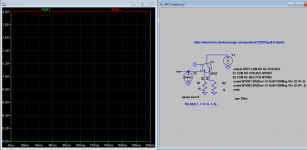
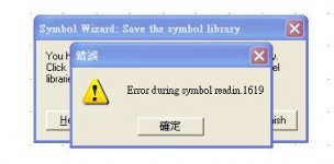
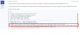
Hi Koonw, I cannot install the 1619 model in the PSpice, shown the error message as attachedTriode connected 1619 is found here: https://www.audio-talk.co.uk/phpBB3...id=59ab91dc66108c9490a7d6a73a43489f&mode=view
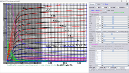
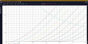
You can plot the triode curve using pentode model just like the actual tube by connecting screen to plate. I usually don't make a separate triode model.
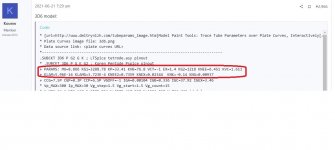
Try this 1619 RCA model:
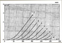
Code:**** 1619 ****************************************** * Created on 03/04/2023 00:29 using paint_kip.jar * www.dmitrynizh.com/tubeparams_image.htm * Plate Curves image file: 1619.png * Data source link: <plate curves URL> *---------------------------------------------------------------------------------- .SUBCKT 1619 P G2 G K ; LTSpice tetrode.asy pinout * .SUBCKT 1619 P G K G2 ; Koren Pentode Pspice pinout + PARAMS: MU=10.26 KG1=2173.88 KP=81.52 KVB=1082.67 VCT=0.07085 EX=1.323 KG2=5368.58 KNEE=17.84 KVC=1.608 + KLAM=3.125E-10 KLAMG=2.354E-4 KD=974.18 KC=0.03139 KR1=7.076E-4 KR2=4.859 KVBG=1.579E-7 KB1=1.293 KB2=1.86 KB3=2 KB4=2.338 KVBGI=5.841E-4 KNK=-0.004269 KNG=0.008371 KNPL=0.6438 KNSL=1.078 KNPR=250.91 KNSR=138.08 + CCG=10.5P CGP=0.35P CCP=12.5P VGOFF=-0.987 IGA=0.006229 IGB=0.2259 IGC=0.41 IGEX=1.872 * Vp_MAX=550 Ip_MAX=400 Vg_step=5 Vg_start=35 Vg_count=18 * X_MIN=67 Y_MIN=17 X_SIZE=789 Y_SIZE=570 FSZ_X=1296 FSZ_Y=736 XYGrid=false * Rp=1400 Vg_ac=20 P_max=15 Vg_qui=-7.5 Vp_qui=300 * showLoadLine=n showIp=y isDHP=n isPP=n isAsymPP=n isUL=n showDissipLimit=y * showIg1=y isInputSnapped=y addLocalNFB=n * XYProjections=n harmonicPlot=y dissipPlot=n * UL=0.43 EG2=300 gridLevel2=y addKink=y isTanhKnee=n advSigmoid=y *---------------------------------------------------------------------------------- RE1 7 0 1G ; DUMMY SO NODE 7 HAS 2 CONNECTIONS E1 7 0 VALUE= ; E1 BREAKS UP LONG EQUATION FOR G1. +{V(G2,K)/KP*LOG(1+EXP((1/MU+(VCT+V(G,K))/SQRT(KVB+V(G2,K)*V(G2,K)))*KP))} RE2 6 0 1G ; DUMMY SO NODE 6 HAS 2 CONNECTIONS E2 6 0 VALUE={(PWR(V(7),EX)+PWRS(V(7),EX))} ; Kg1 times KIT current E4 8 0 VALUE={V(P,K)/KNEE/(KVBGI+V(6)*KVBG)} E5 81 0 VALUE={PWR(V(8),KB1)} E6 82 0 VALUE={PWR(V(8),KB2)} E7 83 0 VALUE={PWR(V(8),KB3)} E8 9 0 VALUE={PWR(1-EXP(-V(81)*(KC+KR1*V(82))/(KD+KR2*V(83))),KB4)*1.5708} RE4 8 0 1 RE5 81 0 1 RE6 82 0 1 RE7 83 0 1 RE8 9 0 1 RE21 21 0 1 E21 21 0 VALUE={V(6)/KG1*V(9)} ; Ip with knee but no slope and no kink RE22 22 0 1 ; E22: kink curr deviation for plate E22 22 0 VALUE={V(21)*LIMIT(KNK-V(G,K)*KNG,0,0.3)*(-ATAN((V(P,K)-KNPL)/KNSL)+ATAN((V(P,K)-KNPR)/KNSR))} G1 P K VALUE={V(21)*(1+KLAMG*V(P,K))+KLAM*V(P,K) + V(22)} G2 G2 K VALUE={V(6)/KG2*(KVC-V(9))/(1+KLAMG*V(P,K)) - V(22)} RCP P K 1G ; FOR CONVERGENCE C1 K G {CCG} ; CATHODE-GRID 1 C2 G P {CGP} ; GRID 1-PLATE C3 K P {CCP} ; CATHODE-PLATE RE23 G 0 1G GG G K VALUE={(IGA+IGB/(IGC+V(P,K)))*(MU/KG1)* +(PWR(V(G,K)-VGOFF,IGEX)+PWRS(V(G,K)-VGOFF,IGEX))} .ENDS *$
Attachments
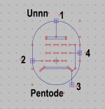
What symbol are you using with this model? You can choose one from the following in 1619 model file, it's Tetrode by default:
.SUBCKT 1619 P G2 G K ; LTSpice tetrode.asy pinout
* .SUBCKT 1619 P G K G2 ; Koren Pentode Pspice pinout
I guess you have to choose "Koren Pentode Pspice pinout", try to uncomment this line and comment out the LTspice line. You also ensure the Pentode symbol you use has the same pins layout (netlist order) as in the model:
*.SUBCKT 1619 P G2 G K ; LTSpice tetrode.asy pinout
.SUBCKT 1619 P G K G2 ; Koren Pentode Pspice pinout
Attachments
Last edited:
Try this 1619 model which does not use Advance Knee, see if it has any problem with installing:
Code:
**** 1619 ******************************************
* Created on 03/06/2023 18:10 using paint_kip.jar
* www.dmitrynizh.com/tubeparams_image.htm
* Plate Curves image file: 1619.png
* Data source link: <plate curves URL>
*----------------------------------------------------------------------------------
.SUBCKT 1619 P G2 G K ; LTSpice tetrode.asy pinout
* .SUBCKT 1619 P G K G2 ; Koren Pentode Pspice pinout
+ PARAMS: MU=10.26 KG1=2173.88 KP=81.52 KVB=270.67 VCT=0.002834 EX=1.323 KG2=4778.04 KNEE=0.1784 KVC=1.571
+ KLAM=3.906E-12 KLAMG=2.613E-4 KNEE2=51.77 KNEX=0.0938  KNK=-0.004269 KNG=0.008371 KNPL=0.6438 KNSL=1.078 KNPR=250.91 KNSR=138.08
+ CCG=10.5P CGP=0.35P CCP=12.5P VGOFF=-1.007 IGA=0.01071 IGB=0.1717 IGC=0.1271 IGEX=1.554
* Vp_MAX=550 Ip_MAX=400 Vg_step=5 Vg_start=35 Vg_count=18
* X_MIN=67 Y_MIN=17 X_SIZE=789 Y_SIZE=570 FSZ_X=1296 FSZ_Y=736 XYGrid=false
* Rp=1400 Vg_ac=20 P_max=15 Vg_qui=-7.5 Vp_qui=300
* showLoadLine=n showIp=y isDHP=n isPP=n isAsymPP=n isUL=n showDissipLimit=y
* showIg1=y isInputSnapped=y addLocalNFB=n
* XYProjections=n harmonicPlot=y dissipPlot=n
* UL=0.43 EG2=300 gridLevel2=y addKink=y isTanhKnee=y advSigmoid=n
*----------------------------------------------------------------------------------
RE1  7 0  1G    ; DUMMY SO NODE 7 HAS 2 CONNECTIONS
E1   7 0  VALUE=  ; E1 BREAKS UP LONG EQUATION FOR G1.
+{V(G2,K)/KP*LOG(1+EXP((1/MU+(VCT+V(G,K))/SQRT(KVB+V(G2,K)*V(G2,K)))*KP))}
RE2  6 0  1G    ; DUMMY SO NODE 6 HAS 2 CONNECTIONS
E2  6 0  VALUE={(PWR(V(7),EX)+PWRS(V(7),EX))} ; Kg1 times KIT current
RE21 21 0 1
E21  21 0 VALUE={V(6)/KG1*ATAN((V(P,K)+KNEX)/KNEE)*TANH(V(P,K)/KNEE2)} ; Ip with knee but no slope and no kink
RE22 22 0 1 ; E22: kink curr deviation for plate
E22  22 0 VALUE={V(21)*LIMIT(KNK-V(G,K)*KNG,0,0.3)*(-ATAN((V(P,K)-KNPL)/KNSL)+ATAN((V(P,K)-KNPR)/KNSR))}
G1   P  K  VALUE={V(21)*(1+KLAMG*V(P,K))+KLAM*V(P,K) + V(22)}
* Alexander Gurskii screen current, see audioXpress 2/2011, with slope and kink added
RE43 43 K 1G ; Dummy
E43  43 G2 VALUE={0} ; Dummy
G2   43 K  VALUE={V(6)/KG2*(KVC-ATAN((V(P,K)+KNEX)/KNEE)*TANH(V(P,K)/KNEE2))/(1+KLAMG*V(P,K))-V(22)}
RCP  P K  1G     ; FOR CONVERGENCE
C1   K G  {CCG}  ; CATHODE-GRID 1
C2   G P  {CGP}  ; GRID 1-PLATE
C3   K P  {CCP}  ; CATHODE-PLATE
RE23 G 0 1G
GG G K VALUE={(IGA+IGB/(IGC+V(P,K)))*(MU/KG1)*
+(PWR(V(G,K)-VGOFF,IGEX)+PWRS(V(G,K)-VGOFF,IGEX))}
.ENDS
*$
Attachments
Here is KC1 model, try it:
Code:
**** KC1 ** Advanced Grid Current **********************************
* Created on 03/06/2023 22:18 using paint_kit.jar 3.1
* www.dmitrynizh.com/tubeparams_image.htm
* Plate Curves image file: kc1.jpg
* Data source link:
*----------------------------------------------------------------------------------
.SUBCKT KC1 1 2 3 ; Plate Grid Cathode
+ PARAMS: CCG=3P  CGP=3.5P CCP=2P
+ MU=28.04 KG1=5940 KP=296 KVB=339 VCT=-0.89 EX=1.4
+ VGOFF=-0.6 IGA=8.7E-4 IGB=0.228 IGC=6.56 IGEX=1.7
* Vp_MAX=300 Ip_MAX=4 Vg_step=1 Vg_start=0 Vg_count=9
* Rp=4000 Vg_ac=55 P_max=0.5 Vg_qui=-48 Vp_qui=300
* X_MIN=53 Y_MIN=51 X_SIZE=638 Y_SIZE=424 FSZ_X=1296 FSZ_Y=736 XYGrid=false
* showLoadLine=n showIp=y isDHT=n isPP=n isAsymPP=n showDissipLimit=y
* showIg1=y gridLevel2=y isInputSnapped=n
* XYProjections=n harmonicPlot=n dissipPlot=n
*----------------------------------------------------------------------------------
E1 7 0 VALUE={V(1,3)/KP*LOG(1+EXP(KP*(1/MU+(VCT+V(2,3))/SQRT(KVB+V(1,3)*V(1,3)))))}
RE1 7 0 1G  ; TO AVOID FLOATING NODES
G1 1 3 VALUE={(PWR(V(7),EX)+PWRS(V(7),EX))/KG1}
RCP 1 3 1G   ; TO AVOID FLOATING NODES
C1 2 3 {CCG} ; CATHODE-GRID
C2 2 1 {CGP} ; GRID=PLATE
C3 1 3 {CCP} ; CATHODE-PLATE
RE2 2 0 1G
EGC 8 0 VALUE={V(2,3)-VGOFF} ; POSITIVE GRID THRESHOLD
GG 2 3 VALUE={(IGA+IGB/(IGC+V(1,3)))*(MU/KG1)*(PWR(V(8),IGEX)+PWRS(V(8),IGEX))}
.ENDS
*$
Attachments
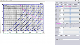
Interesting we can carefully connect the wires and yet the program disconnects some connections. Hopefully it sticks. Thank you for correcting this! 😀I found an open link between R12 and V4 (238V) and a few minor errors now corrected.
Also, thank you so very much for all the files and modifications, you been busy while took the day off. 😳 😀
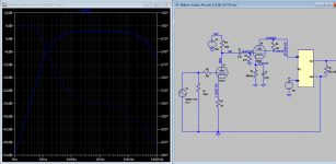
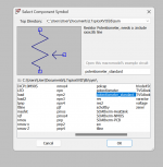
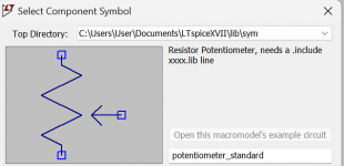
Installed several places as found never know how LTSPice will look for items or when searching find them, so put an extra where I think it should be so remember.Here a potentiometer you can add to sch if you want, or just keyin "Pot" see it shows up.
If you want to model a SPDT switch read here: https://electronics.stackexchange.com/questions/372278/spdt-in-ltspice
I'll try to model when I'm free.
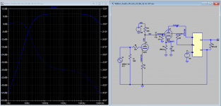
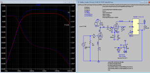
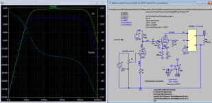
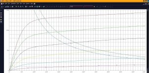
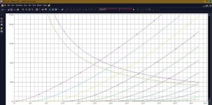
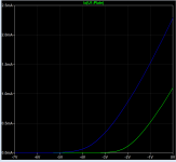
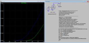
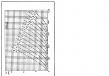
I personally can't run the simulation, still getting an error message despite doing everything per the directions (install the previous files).Here UL/Triode switch is added, now you can see both freq. response curve in one plot.
So, I looked for the potentiometer in the provided file to include it directly and not finding it. Which of the models do we use for the one installed?
I even added the path in the Control Panel and still getting an error.
Another almost hour battling and despite all your work @Koonw , still getting an error code for all of the potentiometers.


Honestly, not seeing the value of switching potentiometers when costs three to five hours of fighting to clear the error codes, I would really appreciate an explanation, please. 🙂
Honestly, not seeing the value of switching potentiometers when costs three to five hours of fighting to clear the error codes, I would really appreciate an explanation, please. 🙂
Thanks Koonw, my hero 🙏Here is KC1 model, try it:
Code:**** KC1 ** Advanced Grid Current ********************************** * Created on 03/06/2023 22:18 using paint_kit.jar 3.1 * www.dmitrynizh.com/tubeparams_image.htm * Plate Curves image file: kc1.jpg * Data source link: *---------------------------------------------------------------------------------- .SUBCKT KC1 1 2 3 ; Plate Grid Cathode + PARAMS: CCG=3P CGP=3.5P CCP=2P + MU=28.04 KG1=5940 KP=296 KVB=339 VCT=-0.89 EX=1.4 + VGOFF=-0.6 IGA=8.7E-4 IGB=0.228 IGC=6.56 IGEX=1.7 * Vp_MAX=300 Ip_MAX=4 Vg_step=1 Vg_start=0 Vg_count=9 * Rp=4000 Vg_ac=55 P_max=0.5 Vg_qui=-48 Vp_qui=300 * X_MIN=53 Y_MIN=51 X_SIZE=638 Y_SIZE=424 FSZ_X=1296 FSZ_Y=736 XYGrid=false * showLoadLine=n showIp=y isDHT=n isPP=n isAsymPP=n showDissipLimit=y * showIg1=y gridLevel2=y isInputSnapped=n * XYProjections=n harmonicPlot=n dissipPlot=n *---------------------------------------------------------------------------------- E1 7 0 VALUE={V(1,3)/KP*LOG(1+EXP(KP*(1/MU+(VCT+V(2,3))/SQRT(KVB+V(1,3)*V(1,3)))))} RE1 7 0 1G ; TO AVOID FLOATING NODES G1 1 3 VALUE={(PWR(V(7),EX)+PWRS(V(7),EX))/KG1} RCP 1 3 1G ; TO AVOID FLOATING NODES C1 2 3 {CCG} ; CATHODE-GRID C2 2 1 {CGP} ; GRID=PLATE C3 1 3 {CCP} ; CATHODE-PLATE RE2 2 0 1G EGC 8 0 VALUE={V(2,3)-VGOFF} ; POSITIVE GRID THRESHOLD GG 2 3 VALUE={(IGA+IGB/(IGC+V(1,3)))*(MU/KG1)*(PWR(V(8),IGEX)+PWRS(V(8),IGEX))} .ENDS *$
Remove the ".txt" from the file attached and put it the following or any subdir in the searchable path, eg:
C:\Users\User\Documents\LTspiceXVII\lib\sub
To use it, you need to point to directory , key in "pot" and insert into schematics, added ".inc potentiometer_standard.lib" (this instruction is displayed with symbol displayed)
C:\Users\User\Documents\LTspiceXVII\lib\sub
To use it, you need to point to directory , key in "pot" and insert into schematics, added ".inc potentiometer_standard.lib" (this instruction is displayed with symbol displayed)
Attachments
Last edited:
- Home
- Amplifiers
- Tubes / Valves
- Vacuum Tube SPICE Models