You can use a pentode model also in triode mode when the pentode model is able to deliver correct plate and g2 currents for ANY Vg2 (not just for ONE Vg2).
I'm not 100% sure, but I guess an Ayumi pentode model behaves so.
That makes sense. Thank you.
I stumbled on a library of LTspice models on GitHub that looks to consist of models created using two older modeling packages (EXCEM Vacuum Tube Modeling Package and Motega) plus a bunch of random models of all types. They claim to be formatted for LTSpice (although some of the comments reference PSpice) but I have not used any in a simulation yet.
Notable for my use is that the file contains a pentode model for the 6J52P (or 6Z52P) using the EXCEM methods. Do their models still hold up?
I increased the Mu to (100+) get better fit. In circuit, the Mu is less (60-88)
I had to do the same thing with 6CW4a -- even though mu measures 68, the model fits the data best @ mu=100
Hi Ray
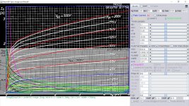
There's an ECC82 triode model missed in my lib. So I had a closer look to frank's data sheet collection, whether there is a datasheet containing sufficient grid current curves. And there is!!
Thanks, Adrian! I'll check it out.
Hi Ray,
you are welcome!
You mentioned that you prefer tubes which are still in production. It seems that the JJ ECC802S has a quite similar construction as the Philips E82CC.
Cheers, Adrian
you are welcome!
You mentioned that you prefer tubes which are still in production. It seems that the JJ ECC802S has a quite similar construction as the Philips E82CC.
Cheers, Adrian
Thanks, Adrian. It's not that I think current production tubes are better quality than NOS (they probably are not). I just try to avoid using a tube that might become expensive and difficult to find (like the 7199) when another tube is readily available. This gives users a choice to go with either NOS or new production of a particular tube as they prefer.
I also take care to operate tubes in the "center bias" region of their load line so as to be fairly insensitive to variations in tube parameters (within reason, of course). Exotic tubes do have their appeal, I'll admit, but I don't have a well-stocked junk box so I would have to go out of my way to find and use them.
Anyway, thanks again for sharing your good work with the rest of us.
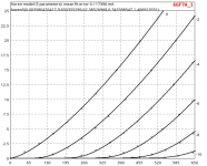
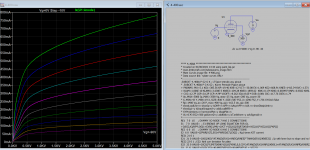
6GF7A LTspice model
Code:
* ==============================================================
* 6GF7A_1 section #1 LTSpice model
* Koren model (5 parameters): mean fit error 0.117396mA
* Traced by Wayne Clay on 09/28/2007 using Curve Captor v0.9.1
* from General Electric data sheet
* ==============================================================
.subckt 6GF7A_1 P G K
Bp P K I=
+ (0.0035804764m)*uramp(V(P,K)*ln(1.0+exp((9.650355186)+
+ (9.650355186)*(62.38526966)*V(G,K)/sqrt((6.34339812k)+
+ (V(P,K))**2)))/(9.650355186))**(1.406913552)
Cgk G K 3.1p ; 0.7p added
Cpk P K 0.96p ; 0.7p added
Cgp G P 5.3p ; 0.7p added
Rpk P K 1G ; to avoid floating nodes
d3 G K dx1
.model dx1 d(is=1n rs=2k cjo=1pf N=1.5 tt=1n)
.ends 6GF7A_1
* ==============================================================
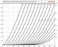
* 6GF7A_2 section #2 LTSpice model
* Modified Koren model (8 parameters): mean fit error 2.92811mA
* Traced by Wayne Clay on 10/09/2013 using Curve Captor v0.9.1
* from General Electric data sheet
* ==============================================================-
.subckt 6GF7A_2 P G K
Bp P K I=
+ (0.3285499321m)*uramp(V(P,K)*ln(1.0+(0.01337326711)+exp((3.472820984)+
+ (3.472820984)*((6.685844309)+(-8.131246619m)*V(G,K))*V(G,K)/sqrt((36.15141626)**2+
+ (V(P,K)-(3.75882527))**2)))/(3.472820984))**(1.393485883)
Cgk G K 6.7p ; 0.2p added
Cpk P K 1.6p ; 0.2p added
Cgp G P 9.7p ; 0.7p added
Rpk P K 1G ; to avoid floating nodes
d3 G K dx1
.model dx1 d(is=1n rs=2k cjo=1pf N=1.5 tt=1n)
.ends 6GF7A_2Attachments
Hi all
Happy new year
Does anyone tried the 4-400A by EIMAC ltspice model in tetrode mode?
I was looking for them along time but no any luck...
Thanks in davnce
Best regards
Chris
Happy new year
Does anyone tried the 4-400A by EIMAC ltspice model in tetrode mode?
I was looking for them along time but no any luck...
Thanks in davnce
Best regards
Chris
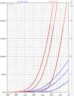
4-400a trial model.
Original curve can not be used by Paint Tool directly, only few data point are extracted, eg Vg=-90V Ia=90mA, Va=4500V. A more accurate model would be to extract more data points.
Original curve can not be used by Paint Tool directly, only few data point are extracted, eg Vg=-90V Ia=90mA, Va=4500V. A more accurate model would be to extract more data points.
Code:
**** 4_400a ******************************************
* Created on 01/04/2021 18:00 using paint_kip.jar
* [url=http://www.dmitrynizh.com/tubeparams_image.htm]Model Paint Tools: Trace Tube Parameters over Plate Curves, Interactively[/url]
* Plate Curves image file: 4-400.png
* Data source link: <plate curves URL>
*----------------------------------------------------------------------------------
.SUBCKT 4_400A P G2 G K ; LTSpice tetrode.asy pinout
* .SUBCKT 4_400A P G K G2 ; Koren Pentode Pspice pinout
+ PARAMS: MU=5.1 KG1=2765.53 KP=20.6 KVB=12 VCT=0.2 EX=1.4 KG2=14864.64 KNEE=188.12 KVC=2.184
+ KLAM=2.125E-8 KLAMG=2.977E-6   KNK=-0.044 KNG=0.006 KNPL=50 KNSL=11 KNPR=120 KNSR=29
+ CCG=12.5P CGP=0.12P CCP=4.7P VGOFF=-9.76 IGA=0.001 IGB=0.3 IGC=8 IGEX=2
* Vp_MAX=4500 Ip_MAX=2000 Vg_step=50 Vg_start=100 Vg_count=30
* X_MIN=113 Y_MIN=73 X_SIZE=741 Y_SIZE=500 FSZ_X=1296 FSZ_Y=736 XYGrid=true
* Rp=1400 Vg_ac=20 P_max=400 Vg_qui=-625 Vp_qui=300
* showLoadLine=n showIp=y isDHP=n isPP=n isAsymPP=n isUL=n showDissipLimit=y
* showIg1=y isInputSnapped=y addLocalNFB=n
* XYProjections=n harmonicPlot=y dissipPlot=n
* UL=0.43 EG2=500 gridLevel2=y addKink=y isTanhKnee=n advSigmoid=n
*----------------------------------------------------------------------------------
RE1  7 0  1G    ; DUMMY SO NODE 7 HAS 2 CONNECTIONS
E1   7 0  VALUE=  ; E1 BREAKS UP LONG EQUATION FOR G1.
+{V(G2,K)/KP*LOG(1+EXP((1/MU+(VCT+V(G,K))/SQRT(KVB+V(G2,K)*V(G2,K)))*KP))}
RE2  6 0  1G    ; DUMMY SO NODE 6 HAS 2 CONNECTIONS
E2  6 0  VALUE={(PWR(V(7),EX)+PWRS(V(7),EX))} ; Kg1 times KIT current
RE21 21 0 1
E21  21 0 VALUE={V(6)/KG1*ATAN(V(P,K)/KNEE)} ; Ip with knee but no slope and no kink
RE22 22 0 1 ; E22: kink curr deviation for plate
E22  22 0 VALUE={V(21)*LIMIT(KNK-V(G,K)*KNG,0,0.3)*(-ATAN((V(P,K)-KNPL)/KNSL)+ATAN((V(P,K)-KNPR)/KNSR))}
G1   P  K  VALUE={V(21)*(1+KLAMG*V(P,K))+KLAM*V(P,K) + V(22)}
* Alexander Gurskii screen current, see audioXpress 2/2011, with slope and kink added
RE43 43 K 1G ; Dummy
E43  43 G2 VALUE={0} ; Dummy
G2   43 K  VALUE={V(6)/KG2*(KVC-ATAN(V(P,K)/KNEE))/(1+KLAMG*V(P,K))-V(22)}
RCP  P K  1G     ; FOR CONVERGENCE
C1   K G  {CCG}  ; CATHODE-GRID 1
C2   G P  {CGP}  ; GRID 1-PLATE
C3   K P  {CCP}  ; CATHODE-PLATE
RE23 G 0 1G
GG G K VALUE={(IGA+IGB/(IGC+V(P,K)))*(MU/KG1)*
+(PWR(V(G,K)-VGOFF,IGEX)+PWRS(V(G,K)-VGOFF,IGEX))}
.ENDS
Attachments
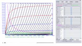
There are other more comprehensive curves for 4-400 tubes from their European subs namely the QB4/1100 and others http://www.frank.mif.pg.gda.pl/sheets/030/q/QB4-1100.pdf
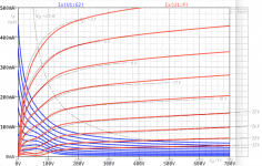
Thank you, here is the updated model for 4-400A:
Code:
* Created on 01/06/2021 13:10 using paint_kip.jar
* [url=http://www.dmitrynizh.com/tubeparams_image.htm]Model Paint Tools: Trace Tube Parameters over Plate Curves, Interactively[/url]
* Plate Curves image file: 4-400.png
* Data source link: <plate curves URL>
*----------------------------------------------------------------------------------
.SUBCKT 4_400A P G2 G K ; LTSpice tetrode.asy pinout
* .SUBCKT 4_400A P G K G2 ; Koren Pentode Pspice pinout
+ PARAMS: MU=5.1 KG1=385.56 KP=19.46 KVB=12 VCT=-30.08 EX=1.069 KG2=668.91 KNEE=1413.34 KVC=1.571
+ KLAM=1.006E-10 KLAMG=3.638E-5 KNEE2=104.28 KNEX=1859.62  KNK=0.174 KNG=0.003497 KNPL=0.6562 KNSL=32.52 KNPR=263.2 KNSR=167.5
+ CCG=12.7P CGP=0.12P CCP=4.9P VGOFF=-8.262 IGA=8.6E-4 IGB=0.081 IGC=117.76 IGEX=1.74
* Vp_MAX=5000 Ip_MAX=3500 Vg_step=25 Vg_start=200 Vg_count=30
* X_MIN=43 Y_MIN=19 X_SIZE=830 Y_SIZE=587 FSZ_X=1296 FSZ_Y=736 XYGrid=false
* Rp=1400 Vg_ac=20 P_max=400 Vg_qui=-162.5 Vp_qui=300
* showLoadLine=n showIp=y isDHP=n isPP=n isAsymPP=n isUL=n showDissipLimit=y
* showIg1=y isInputSnapped=y addLocalNFB=n
* XYProjections=n harmonicPlot=y dissipPlot=n
* UL=0.43 EG2=500 gridLevel2=y addKink=y isTanhKnee=y advSigmoid=n
*----------------------------------------------------------------------------------
RE1  7 0  1G    ; DUMMY SO NODE 7 HAS 2 CONNECTIONS
E1   7 0  VALUE=  ; E1 BREAKS UP LONG EQUATION FOR G1.
+{V(G2,K)/KP*LOG(1+EXP((1/MU+(VCT+V(G,K))/SQRT(KVB+V(G2,K)*V(G2,K)))*KP))}
RE2  6 0  1G    ; DUMMY SO NODE 6 HAS 2 CONNECTIONS
E2  6 0  VALUE={(PWR(V(7),EX)+PWRS(V(7),EX))} ; Kg1 times KIT current
RE21 21 0 1
E21  21 0 VALUE={V(6)/KG1*ATAN((V(P,K)+KNEX)/KNEE)*TANH(V(P,K)/KNEE2)} ; Ip with knee but no slope and no kink
RE22 22 0 1 ; E22: kink curr deviation for plate
E22  22 0 VALUE={V(21)*LIMIT(KNK-V(G,K)*KNG,0,0.3)*(-ATAN((V(P,K)-KNPL)/KNSL)+ATAN((V(P,K)-KNPR)/KNSR))}
G1   P  K  VALUE={V(21)*(1+KLAMG*V(P,K))+KLAM*V(P,K) + V(22)}
* Alexander Gurskii screen current, see audioXpress 2/2011, with slope and kink added
RE43 43 K 1G ; Dummy
E43  43 G2 VALUE={0} ; Dummy
G2   43 K  VALUE={V(6)/KG2*(KVC-ATAN((V(P,K)+KNEX)/KNEE)*TANH(V(P,K)/KNEE2))/(1+KLAMG*V(P,K))-V(22)}
RCP  P K  1G     ; FOR CONVERGENCE
C1   K G  {CCG}  ; CATHODE-GRID 1
C2   G P  {CGP}  ; GRID 1-PLATE
C3   K P  {CCP}  ; CATHODE-PLATE
RE23 G 0 1G
GG G K VALUE={(IGA+IGB/(IGC+V(P,K)))*(MU/KG1)*
+(PWR(V(G,K)-VGOFF,IGEX)+PWRS(V(G,K)-VGOFF,IGEX))}
.ENDS
*$
Attachments
Attachments
Last edited:
And here is the Ayumi pentode model:
Code:
*
* Generic pentode model: EL34
* Copyright 2003--2008 by Ayumi Nakabayashi, All rights reserved.
* Version 3.10, Generated on Sat Mar  8 22:42:48 2008
*            Plate
*            | Screen Grid
*            | |  Control Grid
*            | |  |  Cathode
*            | |  |  |
.SUBCKT EL34 A G2 G1 K
BGG   GG   0 V=V(G1,K)+0.29360503
BM1   M1   0 V=(0.040003405*(URAMP(V(G2,K))+1e-10))**-0.73308055
BM2   M2   0 V=(0.67171782*(URAMP(V(GG)+URAMP(V(G2,K))/8.2063559)))**2.2330806
BP    P    0 V=0.0033402929*(URAMP(V(GG)+URAMP(V(G2,K))/12.216969))**1.5
BIK   IK   0 V=U(V(GG))*V(P)+(1-U(V(GG)))*0.0019762451*V(M1)*V(M2)
BIG   IG   0 V=0.0016701465*URAMP(V(G1,K))**1.5*(URAMP(V(G1,K))/(URAMP(V(A,K))+URAMP(V(G1,K)))*1.2+0.4)
BIK2  IK2  0 V=V(IK,IG)*(1-0.4*(EXP(-URAMP(V(A,K))/URAMP(V(G2,K))*15)-EXP(-15)))
BIG2T IG2T 0 V=V(IK2)*(0.87617414*(1-URAMP(V(A,K))/(URAMP(V(A,K))+10))**1.5+0.12382586)
BIK3  IK3  0 V=V(IK2)*(URAMP(V(A,K))+1250)/(URAMP(V(G2,K))+1250)
BIK4  IK4  0 V=V(IK3)-URAMP(V(IK3)-(0.0020885491*(URAMP(V(A,K))+URAMP(URAMP(V(G2,K))-URAMP(V(A,K))))**1.5))
BIP   IP   0 V=URAMP(V(IK4,IG2T)-URAMP(V(IK4,IG2T)-(0.0020885491*URAMP(V(A,K))**1.5)))
BIAK  A    K I=V(IP)+1e-10*V(A,K)
BIG2  G2   K I=URAMP(V(IK4,IP))
BIGK  G1   K I=V(IG)
* CAPS
CGA   G1  A  1.1p
CGK   G1  K  9.1p
C12   G1  G2 6.1p
CAK   A   K  8.4p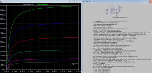
.ENDSWell, my bad. Thanks for the models but I wasn't paying attention. Those are for EL34 models where grid 3 is assumed to be tied to the cathode. But I was looking for something like where all three grids, plate and cathode are included in the spice model. I have an .asy of a pentode but can't find a spice file to support it.
Attachments
Nearly all "pentode" models are actually tetrode models so you would use the LTspice tetrode.asy symbol instead of the LTspice pentode symbol. The suppressor grid is rarely used as a true signal terminal in mainstream pentode output tubes, being tied to the cathode either internally or externally, depending on the tube. This is a detail you have to pay attention to when you construct an amplifier but is not important when running simulations.
FYI, I have never run across a pentode or beam power tetrode SPICE model that actually models the suppressor grid.
FYI, I have never run across a pentode or beam power tetrode SPICE model that actually models the suppressor grid.
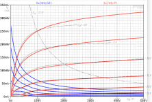
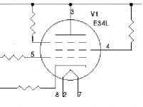
I agree with that. I ran across a Steve Bench schematic of an EL34 tube amp and he used the suppressor grid tied to the plate through a 1K resistor. To spice that I would need a pentode spice model I think? All of the other EL34 circuits I've spiced have the suppressor grid tied to the cathode internally.Here's the circuit.
Attachments

You would but, as I said, I've never seen a EL34 model that models the suppressor grid. But in this amp the EL34 is operating more-or-less in triode mode. I believe the following link is where you found this schematic, and the description refers to it as a triode-mode amplifier.
Steve's Tube Pages
It would be better to model this amplifier using a triode-strapped SPICE model with the triode.asy symbol instead. For simulation purposes, you can ignore the 1k and 1.5k resistors from the suppressor and screen grids to the plate.
Here is a SPICE model for the EL34, triode strapped.
Code:
*
* Generic triode model: EL34T
* Copyright 2003--2008 by Ayumi Nakabayashi, All rights reserved.
* Version 3.10, Generated on Sat Mar  8 22:42:48 2008
*             Plate
*             | Grid
*             | | Cathode
*             | | |
.SUBCKT EL34T A G K
BGG   GG   0 V=V(G,K)+0.29360503
BM1   M1   0 V=(0.040003405*(URAMP(V(A,K))+1e-10))**-0.73308055
BM2   M2   0 V=(0.67171782*(URAMP(V(GG)+URAMP(V(A,K))/8.2063559)+1e-10))**2.2330806
BP    P    0 V=0.0033402929*(URAMP(V(GG)+URAMP(V(A,K))/12.216969)+1e-10)**1.5
BIK   IK   0 V=U(V(GG))*V(P)+(1-U(V(GG)))*0.0019762451*V(M1)*V(M2)
BIG   IG   0 V=0.0016701465*URAMP(V(G,K))**1.5*(URAMP(V(G,K))/(URAMP(V(A,K))+URAMP(V(G,K)))*1.2+0.4)
BIAK  A    K I=URAMP(V(IK,IG)-URAMP(V(IK,IG)-(0.0020885491*URAMP(V(A,K))**1.5)))+1e-10*V(A,K)
BIGK  G    K I=V(IG)
* CAPS
CGA   G    A 7.2p
CGK   G    K 9.1p
CAK   A    K 8.4p
.ENDS
Last edited:
- Home
- Amplifiers
- Tubes / Valves
- Vacuum Tube SPICE Models