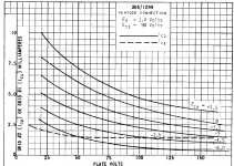
The actual or real limitation is screen dissipation should not be exceeded if no max screen voltage is specified, I think.
That is, it is 300v .... in fact I read about those who are comfortable polasizing it at 220v
Hi Koonw, I am looking for PSpice Pentode & Triode models of 1F5-G, 3D6, 6SG7. Please help, Thank You.


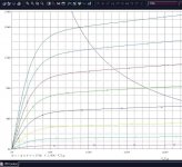
3D6 model:
Code:
* [url=http://www.dmitrynizh.com/tubeparams_image.htm]Model Paint Tools: Trace Tube Parameters over Plate Curves, Interactively[/url]
* Plate Curves image file: 3d6.png
* Data source link: <plate curves URL>
*----------------------------------------------------------------------------------
.SUBCKT 3D6 P G2 G K ; LTSpice tetrode.asy pinout
* .SUBCKT 3D6 P G K G2 ; Koren Pentode Pspice pinout
+ PARAMS: MU=8.866 KG1=3288.78 KP=33.41 KVB=76.8 VCT=-1 EX=1.4 KG2=1218 KNEE=6.451 KVC=1.611
+ KLAM=5.96E-16 KLAMG=3.723E-4 KNEE2=0.7359 KNEX=0.02344  KNK=-0.14 KNG=0.00937
+ CCG=7.5P CGP=0.3P CCP=6.5P VGOFF=-1 IGA=0.00104 IGB=0.336 IGC=37.92 IGEX=3.46
* Vp_MAX=300 Ip_MAX=30 Vg_step=1.5 Vg_start=1.5 Vg_count=15
* X_MIN=34 Y_MIN=168 X_SIZE=834 Y_SIZE=417 FSZ_X=1296 FSZ_Y=736 XYGrid=false
* Rp=1400 Vg_ac=20 P_max=4.5 Vg_qui=-9 Vp_qui=300
* showLoadLine=n showIp=y isDHP=n isPP=n isAsymPP=n isUL=n showDissipLimit=y
* showIg1=y isInputSnapped=y addLocalNFB=n
* XYProjections=n harmonicPlot=y dissipPlot=n
* UL=0.43 EG2=90 gridLevel2=y addKink=n isTanhKnee=y advSigmoid=n
*----------------------------------------------------------------------------------
RE1  7 0  1G    ; DUMMY SO NODE 7 HAS 2 CONNECTIONS
E1   7 0  VALUE=  ; E1 BREAKS UP LONG EQUATION FOR G1.
+{V(G2,K)/KP*LOG(1+EXP((1/MU+(VCT+V(G,K))/SQRT(KVB+V(G2,K)*V(G2,K)))*KP))}
RE2  6 0  1G    ; DUMMY SO NODE 6 HAS 2 CONNECTIONS
E2  6 0  VALUE={(PWR(V(7),EX)+PWRS(V(7),EX))} ; Kg1 times KIT current
G1   P K  VALUE={V(6)/KG1*ATAN((V(P,K)+KNEX)/KNEE)*TANH(V(P,K)/KNEE2)*(1+KLAMG*V(P,K))+KLAM*V(P,K)}
* Alexander Gurskii screen current, see audioXpress 2/2011
RE4K 4K K 1G ; Dummy, per Alex request
E4K 4K  4 VALUE={0} ; Dummy, per Alex request
G4K 4K K VALUE={V(6)/KG2*(KVC-ATAN((V(P,K)+KNEX)/KNEE)*TANH(V(P,K)/KNEE2))/(1+KLAMG*V(P,K))}
RCP  P K  1G     ; FOR CONVERGENCE
C1   K G  {CCG}  ; CATHODE-GRID 1
C2   G P  {CGP}  ; GRID 1-PLATE
C3   K P  {CCP}  ; CATHODE-PLATE
RE23 G 0 1G
GG G K VALUE={(IGA+IGB/(IGC+V(P,K)))*(MU/KG1)*
+(PWR(V(G,K)-VGOFF,IGEX)+PWRS(V(G,K)-VGOFF,IGEX))}
.ENDS
*$
Attachments

Hello Koonw, thank you very much
The 3D6 pentode model worked great with PSpice! Please provide the Triode model together 🙂


The 3D6 pentode model worked great with PSpice! Please provide the Triode model together 🙂
An externally hosted image should be here but it was not working when we last tested it.
Last edited:

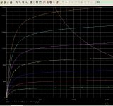
6SG7 model:
Code:
* [URL="http://www.dmitrynizh.com/tubeparams_image.htm"]www.dmitrynizh.com/tubeparams_image.htm[/URL]
* Plate Curves image file: 6sg7.png
* Data source link: <plate curves URL>
*----------------------------------------------------------------------------------
.SUBCKT 6SG7 P G2 G K ; LTSpice tetrode.asy pinout
* .SUBCKT 6SG7 P G K G2 ; Koren Pentode Pspice pinout
+ PARAMS: MU=48.75 KG1=706.16 KP=40.28 KVB=36.69 VCT=-1.648 EX=1.61 KG2=865.83 KNEE=13.03 KVC=2.213
+ KLAM=7.226E-11 KLAMG=6.961E-5 KNEE2=5.919 KNEX=0.0525  KNK=-0.044 KNG=0.006
+ CCG=8.5P CGP=0.003P CCP=7P VGOFF=-0.6 IGA=0.001 IGB=0.3 IGC=8 IGEX=2
* Vp_MAX=500 Ip_MAX=12.5 Vg_step=2 Vg_start=0 Vg_count=20
* X_MIN=75 Y_MIN=105 X_SIZE=556 Y_SIZE=562 FSZ_X=1296 FSZ_Y=736 XYGrid=false
* Rp=1400 Vg_ac=20 P_max=3 Vg_qui=-19 Vp_qui=300
* showLoadLine=n showIp=y isDHP=n isPP=n isAsymPP=n isUL=n showDissipLimit=y
* showIg1=y isInputSnapped=y addLocalNFB=n
* XYProjections=n harmonicPlot=y dissipPlot=n
* UL=0.43 EG2=100 gridLevel2=y addKink=n isTanhKnee=y advSigmoid=n
*----------------------------------------------------------------------------------
RE1  7 0  1G    ; DUMMY SO NODE 7 HAS 2 CONNECTIONS
E1   7 0  VALUE=  ; E1 BREAKS UP LONG EQUATION FOR G1.
+{V(G2,K)/KP*LOG(1+EXP((1/MU+(VCT+V(G,K))/SQRT(KVB+V(G2,K)*V(G2,K)))*KP))}
RE2  6 0  1G    ; DUMMY SO NODE 6 HAS 2 CONNECTIONS
E2  6 0  VALUE={(PWR(V(7),EX)+PWRS(V(7),EX))} ; Kg1 times KIT current
G1   P K  VALUE={V(6)/KG1*ATAN((V(P,K)+KNEX)/KNEE)*TANH(V(P,K)/KNEE2)*(1+KLAMG*V(P,K))+KLAM*V(P,K)}
* Alexander Gurskii screen current, see audioXpress 2/2011
RE4K 4K K 1G ; Dummy, per Alex request
E4K 4K  4 VALUE={0} ; Dummy, per Alex request
G4K 4K K VALUE={V(6)/KG2*(KVC-ATAN((V(P,K)+KNEX)/KNEE)*TANH(V(P,K)/KNEE2))/(1+KLAMG*V(P,K))}
RCP  P K  1G     ; FOR CONVERGENCE
C1   K G  {CCG}  ; CATHODE-GRID 1
C2   G P  {CGP}  ; GRID 1-PLATE
C3   K P  {CCP}  ; CATHODE-PLATE
RE23 G 0 1G
GG G K VALUE={(IGA+IGB/(IGC+V(P,K)))*(MU/KG1)*
+(PWR(V(G,K)-VGOFF,IGEX)+PWRS(V(G,K)-VGOFF,IGEX))}
.ENDS
*$
Attachments
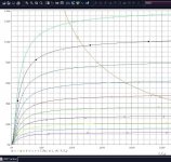
1f5g model:
Code:
*** 1F5G ******************************************
* Created on 06/22/2021 11:18 using paint_kip.jar
* [url=http://www.dmitrynizh.com/tubeparams_image.htm]Model Paint Tools: Trace Tube Parameters over Plate Curves, Interactively[/url]
* Plate Curves image file: 1f5g.png
* Data source link: <plate curves URL>
*----------------------------------------------------------------------------------
.SUBCKT 1F5G P G2 G K ; LTSpice tetrode.asy pinout
* .SUBCKT 1F5G P G K G2 ; Koren Pentode Pspice pinout
+ PARAMS: MU=12.8 KG1=5588 KP=122.38 KVB=12 VCT=0.2 EX=1.4 KG2=16296 KNEE=8.532 KVC=2.236
+ KLAM=2.5E-8 KLAMG=6.48E-4 KNEE2=26.13 KNEX=69.3  KNK=-0.044 KNG=0.006 KNPL=50 KNSL=11 KNPR=120 KNSR=29
+ CCG=3P CGP=1.4P CCP=1.9P VGOFF=-0.6 IGA=0.001 IGB=0.3 IGC=8 IGEX=2
* Vp_MAX=400 Ip_MAX=20 Vg_step=3 Vg_start=0 Vg_count=9
* X_MIN=36 Y_MIN=113 X_SIZE=803 Y_SIZE=404 FSZ_X=1296 FSZ_Y=736 XYGrid=false
* Rp=1400 Vg_ac=20 P_max=1.75 Vg_qui=-12 Vp_qui=300
* showLoadLine=n showIp=y isDHP=n isPP=n isAsymPP=n isUL=n showDissipLimit=y
* showIg1=y isInputSnapped=y addLocalNFB=n
* XYProjections=n harmonicPlot=y dissipPlot=n
* UL=0.43 EG2=135 gridLevel2=y addKink=y isTanhKnee=y advSigmoid=n
*----------------------------------------------------------------------------------
RE1  7 0  1G    ; DUMMY SO NODE 7 HAS 2 CONNECTIONS
E1   7 0  VALUE=  ; E1 BREAKS UP LONG EQUATION FOR G1.
+{V(G2,K)/KP*LOG(1+EXP((1/MU+(VCT+V(G,K))/SQRT(KVB+V(G2,K)*V(G2,K)))*KP))}
RE2  6 0  1G    ; DUMMY SO NODE 6 HAS 2 CONNECTIONS
E2  6 0  VALUE={(PWR(V(7),EX)+PWRS(V(7),EX))} ; Kg1 times KIT current
RE21 21 0 1
E21  21 0 VALUE={V(6)/KG1*ATAN((V(P,K)+KNEX)/KNEE)*TANH(V(P,K)/KNEE2)} ; Ip with knee but no slope and no kink
RE22 22 0 1 ; E22: kink curr deviation for plate
E22  22 0 VALUE={V(21)*LIMIT(KNK-V(G,K)*KNG,0,0.3)*(-ATAN((V(P,K)-KNPL)/KNSL)+ATAN((V(P,K)-KNPR)/KNSR))}
G1   P  K  VALUE={V(21)*(1+KLAMG*V(P,K))+KLAM*V(P,K) + V(22)}
* Alexander Gurskii screen current, see audioXpress 2/2011, with slope and kink added
RE43 43 K 1G ; Dummy
E43  43 G2 VALUE={0} ; Dummy
G2   43 K  VALUE={V(6)/KG2*(KVC-ATAN((V(P,K)+KNEX)/KNEE)*TANH(V(P,K)/KNEE2))/(1+KLAMG*V(P,K))-V(22)}
RCP  P K  1G     ; FOR CONVERGENCE
C1   K G  {CCG}  ; CATHODE-GRID 1
C2   G P  {CGP}  ; GRID 1-PLATE
C3   K P  {CCP}  ; CATHODE-PLATE
RE23 G 0 1G
GG G K VALUE={(IGA+IGB/(IGC+V(P,K)))*(MU/KG1)*
+(PWR(V(G,K)-VGOFF,IGEX)+PWRS(V(G,K)-VGOFF,IGEX))}
.ENDS
*$
Attachments

Hi all,
I worked the last weeks on a new generic Triode version of mine, the version i5. It has a more accurate grid current model, which will be noticeable in high-gm triodes.
I experienced that weak points are better found, when somebody else but not the inventor does test a new thing.
So, is there anybody who would like to test my PhilipsECG 6922 i5 prototype?
You can just play with it - including "misuse" like connected in wrong way, overdrive it, etc. 🙄
Any convergence problems or obviously wrong result would awake my interest 😉
Thanks
Adrian
Anything I can do to help. I have plenty of modeled circuits using 6DJ8 which I can change to torture the i5 model. How about trying contact potential biasing? Perhaps running the model with very low grid-cathode voltage on the order of -0.7V? With an actual 6DJ8 that should induce some grid current. I can send screenshots of error messages, etc.
So, is there anybody who would like to test my PhilipsECG 6922 i5 prototype?
I do a lot of designs using the 6922 so I would be willing to try your new model. I have several 6DJ8/E88CC models that I use, and I have a couple of circuits that don't work well with certain models. This should be a good test.
I do a lot of designs using the 6922 so I would be willing to try your new model. I have several 6DJ8/E88CC models that I use, and I have a couple of circuits that don't work well with certain models. This should be a good test.
Hi Ray
That's perfect, thank you! I will send you a PM.
cheers, Adrian
Gents, anyone per chance has a model for the 6HB5? It's a high voltage pentode.
BTW, did you notice that LTspice calls a pentode a 'pentrode'? Tongue in cheek or typo?
Jan
BTW, did you notice that LTspice calls a pentode a 'pentrode'? Tongue in cheek or typo?
Jan
- Home
- Amplifiers
- Tubes / Valves
- Vacuum Tube SPICE Models