Hi Tubemax,
Interesting.....
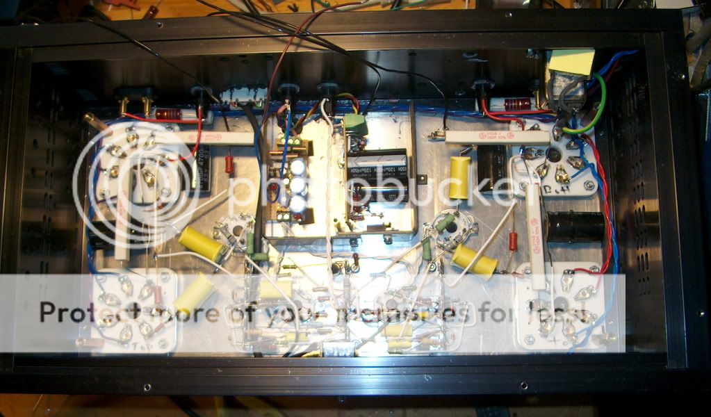
LTP Phase-splitter with CF drive, although I wonder why its designer didnt direct-couple the driver CF's for better drive capabilities to the O/P pair instead of the phase-splitter LTP to the CF's...
I think I need a higher Transconductance tube for the PI set up accordingly if I am to use the 320V supply I have......
Thinking maybe a 7044 or 5687 as I have some of these, The 12BH7 is another that is known to work here but I aint got any! Unfortunately, these are 9-pin all glass valves....
Interesting.....
LTP Phase-splitter with CF drive, although I wonder why its designer didnt direct-couple the driver CF's for better drive capabilities to the O/P pair instead of the phase-splitter LTP to the CF's...
I think I need a higher Transconductance tube for the PI set up accordingly if I am to use the 320V supply I have......
Thinking maybe a 7044 or 5687 as I have some of these, The 12BH7 is another that is known to work here but I aint got any! Unfortunately, these are 9-pin all glass valves....
Hi Alastair E, maybe as a option buying a book ( Audio Reality ) from transcendentsound.com where is in great detail described T8 OTL amplifier based on PL519 triode connected as output tube.
I have this book but due to copyright I can't share anything from it...
In any case designer is using ECC8x driver tubes and not octal ones...but with 8 tubes per channel is claiming 80 WATT's of power or with 4 output tubes 25 WATT on 8 Ohm load.
Max
I have this book but due to copyright I can't share anything from it...
In any case designer is using ECC8x driver tubes and not octal ones...but with 8 tubes per channel is claiming 80 WATT's of power or with 4 output tubes 25 WATT on 8 Ohm load.
Max
Is that V peak (Vpk) or V peak to peak (Vpp), you have not specified which.. You would normally use Vpk, and you can calculate rms power directly as Vpk^2/2RL or Vrms^2/RL if you have a good audio voltmeter. (Note the round off error if you convert Vpk to Vrms - it is significant) You can also use vpp just divide by half and then use the first equation..
More than likely the driver stage cannot quite make up for the voltage losses in the output stage which are quite significant recollecting from my 6C33 OTL debacle.. 😀
IIRC the source impedance of a 6C33 pair in a futterman configuration without feedback is in the vicinity of 12 ohms.. Not sure if the reverse futterman is better or worse than this.
I'd see how much more swing you can extract out of the first stage, and how much additional swing you can get in the second without compromising the sonic qualities you like. I'd run the 6SL7 at half the available supply and play some games with the concertina to maximize voltage swing while trying to keep the current above 6mA. (I like 9 - 10mA for the 6SN7)
FWIW: Mine with all of its design issues still managed to sound really good, noting that my six 6C33 "200W" design only achieved 25W as my driver stages could not deliver the required voltages and current.. It was my epic fail, and given this one works reliably and sounds good you are most of the way there.
One other comment I would make is that in characterizing and matching 6C33 for my amps I saw some very strange behavior when I only ran half the tube. (So long ago I do not remember what, so take it as anecdotal.) Obviously for matching I ran one section at a time and calculated the transconductance based on several different grid voltages and measured plate current at the operating plate voltage. Unloaded there was a measurable difference in linearity and source impedance obviously doubles. I always ran all filaments and just removed pairs when less power was needed.
Kevinkr,
Can you post the circuit of the driver stage you used in the 200W 6c33c..Just interested..Thank's
Regards
M. Gregg
Alastair,
Try putting the 6SL7 in the first stage and turn it up watch the speaker cones....
I will drop the scope on the amp when I get chance curious...
Regards
M. Gregg
Try putting the 6SL7 in the first stage and turn it up watch the speaker cones....
I will drop the scope on the amp when I get chance curious...
Regards
M. Gregg
Hi M Gregg , my opinion is to try the fixed bias for the output tubes ( as I told Alastair ) , because the self-bias increase the output impedance of the amp , and this may be the mainly reason that the amp can not deliver more than 4W into 8ohm load .
Kevinkr,
Can you post the circuit of the driver stage you used in the 200W 6c33c..Just interested..Thank's
Regards
M. Gregg
I'd rather not, there is a reason why over all these years I have never shared it - it is very badly flawed and I'd rather not take the risk that someone would build it not understanding that the design was just bad. At the end I understood why it did not work properly, but got distracted by DHT SE amps. This saga ended about 14yrs ago now, but here is a link to what I wrote about that experience: 6c33
I'd rather not, there is a reason why over all these years I have never shared it - it is very badly flawed and I'd rather not take the risk that someone would build it not understanding that the design was just bad. At the end I understood why it did not work properly, but got distracted by DHT SE amps. This saga ended about 14yrs ago now, but here is a link to what I wrote about that experience: 6c33
Thank's Kevinkr,
Thanks so much for the link..
You know you can learn a lot from other people’s experiences.
I found that building OTL even "feels strange" I guess it’s the current as opposed to the HV that causes this! Even when I have worked on higher current amps the feeling is not the same as OTL... Perhaps it’s because you have to keep reminding yourself think current. Think heat "cooker element”. Or perhaps working on cookers is a greasy pain in the a.. and effects the feeling of OTL build..LOL
Perhaps its the thought that normaly you have a Tx between your mistakes and the speaker..
I must admit they sound good...after going back to my other amps..there now seems to be something missing...a sort of veiling that "was not there before”. Of course it was, just that I had nothing to compare it against. You can hear the OP Tx after listening to OTL..or is that the lack of one. Depends on your point of view I guess.. 🙂
Regards
M. Gregg
Hi M Gregg , my opinion is to try the fixed bias for the output tubes ( as I told Alastair ) , because the self-bias increase the output impedance of the amp , and this may be the mainly reason that the amp can not deliver more than 4W into 8ohm load .
I will look at the output stage and try a few things..just for fun. 🙂
I think I will be experimenting for a while..so much to try..LOL
Thanks for your thoughts I will post any progress..I am also watching your thread with great interest!
Regards
M. Gregg
You 're welcome , and what is the other experiments that you will try ?I will look at the output stage and try a few things..just for fun. 🙂
I think I will be experimenting for a while..so much to try..LOL
Thanks for your thoughts I will post any progress..I am also watching your thread with great interest!
Regards
M. Gregg
Well,
Changing the gate stopper on the first CCS from 1K to 270 Ohm..was a bad idea... so I put the 1k back in place..I guess you could reduce it perhaps to 500 Ohm..this resistor does change the character of the amp...if its over cooked then your going to know about it..
The result of the 270 Ohm was high frequencies amplified were so high you could cut the air with them...
The reduction from 470K to 10k on the PI has given an increase in HF response much more controlled..I still have to put a scope on the amp, however the change is quite obvious.. 🙂
Regards
M. Gregg
Last edited:
Just a thought..
I am thinking of looking at the 2nd stage ccs gate stopper its 270 Ohm at the moment perhaps trying 500 Ohm..it's got to be worth trying a few other values and check the square wave response.. 🙂
After the experience with the first CCS..
Regards
M. Gregg
I am thinking of looking at the 2nd stage ccs gate stopper its 270 Ohm at the moment perhaps trying 500 Ohm..it's got to be worth trying a few other values and check the square wave response.. 🙂
After the experience with the first CCS..
Regards
M. Gregg
Last edited:
Hmm--Thats rather odd!
I'm running 270 ohms in both stages of both channels. I didnt find any huge change in HF (audible) response from what I had there before...
There was a noticable--slight--increase in audible HF when dropping the 470K to 100K on the PI Grid.
Currently, the amp has a flat response to around 150KHz, with minus 3dB at 200....
So, I'm curious as to why there's the huge difference with your version. Maybe interconnecting-leads from MOSFETS are causing some kind of issue with a lower value Gate-Stopper....
Hmm--Thats rather odd!
I'm running 270 ohms in both stages of both channels. I didnt find any huge change in HF (audible) response from what I had there before...
There was a noticable--slight--increase in audible HF when dropping the 470K to 100K on the PI Grid.
Currently, the amp has a flat response to around 150KHz, with minus 3dB at 200....
So, I'm curious as to why there's the huge difference with your version. Maybe interconnecting-leads from MOSFETS are causing some kind of issue with a lower value Gate-Stopper....
Alastair,
The gate stoppers are direct on the mosfet gate...perhaps its the higher frequencies and the 10K grid stopper on the PI..The mid band also became less clear..as soon as I put the 1K back in and its all OK again..this is what is making me wonder about the 2nd stage CCS so I think a 500 Ohm is on the cards..
Regards
M. Gregg
Alastair,
The only other thing is a difference in construction of the 270 Ohm resistors on the ccs...I tried a 1K MF or CC and no difference. perhaps worth trying to get some old CC and try it!
Regards
M. Gregg
The only other thing is a difference in construction of the 270 Ohm resistors on the ccs...I tried a 1K MF or CC and no difference. perhaps worth trying to get some old CC and try it!
Regards
M. Gregg
Might try an anti parasitic bead..just for a laugh..
I have some old time 330 Ohms CC on order.. 🙂
Regards
M. Gregg
I have some old time 330 Ohms CC on order.. 🙂
Regards
M. Gregg
Last edited:
I usually run 1/2w CF for first choice thats what i have a good assortment of.
Together with a bead it usually does the job.
It´s assembly time the total height of amps inside is 8mm higher than the box .
I´ll try to give it flying lessons from 2nd floor balcony and see if it will fit
Probably shaving of some spacers will fix it but it´s very crowded inside.
Together with a bead it usually does the job.
It´s assembly time the total height of amps inside is 8mm higher than the box .
I´ll try to give it flying lessons from 2nd floor balcony and see if it will fit
Probably shaving of some spacers will fix it but it´s very crowded inside.
And here comes the PSU that refuse to fit
*
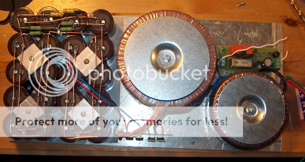
Hi,
Lash some flying leads to it and have a listen..
Then fit a wood plinth around the bottom..or some square section aluminium...or spacers with some brass spaced off the sides to give extra ventilation...You will need it.
🙂
Just for interest..
Can I say the WW resistors on the cathodes of the 6c33c's get hot in use ..I notice one is in line to put heat on the elec capacitor.. 🙂
If all else fails the balcony is an option.... NO it has no wings...LOL <<<<< OTL glider
You will do it a resourceful guy like you ..... 🙂
Regards
M. Gregg
Can I say the WW resistors on the cathodes of the 6c33c's get hot in use ..I notice one is in line to put heat on the elec capacitor.. 🙂
If all else fails the balcony is an option.... NO it has no wings...LOL <<<<< OTL glider
You will do it a resourceful guy like you ..... 🙂
Regards
M. Gregg
Last edited:
The picture is very 2d.
There is some space between about 10mm.
If heat is getting to the caps i have some aluminum insulation tape to try.
If chimney effect doesn´t work i´ll add some fans to get heat out of there.
There is some space between about 10mm.
If heat is getting to the caps i have some aluminum insulation tape to try.
If chimney effect doesn´t work i´ll add some fans to get heat out of there.
- Status
- Not open for further replies.
- Home
- Amplifiers
- Tubes / Valves
- Vacuum Tube OTL power amp!!