I certainly did not find the same with mine. There was no need to warm it beyond an hour.
Ridiculous waste of tube life to leave it running permanently.
I also find it waste of tube life, regardless of the improvement in sound quality it may be. Especially, since we are talking about 12 tubes, not just a couple...
I certainly did not find the same with mine. There was no need to warm it beyond an hour.
Ridiculous waste of tube life to leave it running permanently.
I can only report what I hear. I am always suspicious of subjective bias, but I am nevertheless convinced that this was one of the biggest and most consistent improvements I have made in my system.
Until recently I felt the same as Brett - I couldn't justify leaving the preamp on constantly, simply for reasons of economy and heat generation, but I have changed my mind on that one.
I have said elsewhere that to me, as a physicist, it is a total mystery what could be changing in the circuitry with a timescale longer than a hour or so, but there we are...
Alex
As am I, and as I recall discussing this with Allen over a few emails, and he could suggest no mechanism, and I could measure no real difference, I put it down to wishful thinking. Though I respected Allen a great deal, I never took anything he said as absolute.I can only report what I hear. I am always suspicious of subjective bias
I am also always suspicious of these vast differences purportedly heard, but with no explanation as to what might cause them, and then no evidence that it is so.
FWIW, if I'd bought an RTP3D kit, mine would have had an off switch. The rebuild of my 3C has and will continue to have one.
heater ccs
i have a trimmer for each individual ccs per tube and can trimm from 250 to 370 mA.
i recommend to install a 2mm plug per heater contacht near the tube and the trimmer should have access from the top af the preamp, so you can plug in a multimeter very easy and adjustment gets simple ( i have to turn my rtp upside down and fiddle around in the inside with my voltmeter.
i will build a socket adapter to make measurements less painful
Vtr,
Ok, I can understand that the CCS heater current supply can be made individually adjustable with pots rather than using fixed resistors. However how did you get the 6.3 Volt since as far as I know the heater supply in the RTP3 delivers 12 V as coming from the power supply? Did you make then the whole heater supply 6.3 Volt or did you do it individually per tube? Thanks
airtangent
i have a trimmer for each individual ccs per tube and can trimm from 250 to 370 mA.
i recommend to install a 2mm plug per heater contacht near the tube and the trimmer should have access from the top af the preamp, so you can plug in a multimeter very easy and adjustment gets simple ( i have to turn my rtp upside down and fiddle around in the inside with my voltmeter.
i will build a socket adapter to make measurements less painful
As am I, and as I recall discussing this with Allen over a few emails, and he could suggest no mechanism, and I could measure no real difference, I put it down to wishful thinking. Though I respected Allen a great deal, I never took anything he said as absolute.
I am also always suspicious of these vast differences purportedly heard, but with no explanation as to what might cause them, and then no evidence that it is so.
FWIW, if I'd bought an RTP3D kit, mine would have had an off switch. The rebuild of my 3C has and will continue to have one.
It is also my view that no one's words should be taken as an absolute truth.
At the same time, I have high respect for opinions and advice of people that I appreciate their knowledge and listening appreciation of sound quality.
Whether I understand why certain thing have certain effect is irrelevant to me, the only thing that is relevant to me is what I hear. If doing something improves the sound quality, I'll do it, period.
absolute.
Personal choice, whether it's valid or not.
I run a preamp that eats about 75W continuously, never switching it off would add a couple of hundred bucks to the annual electrical bill.
Leaving stuff on unwarranted is a pet peeve of mine, if i decided to run the tab 24/7, i could not haunt others to pull idle transformers from wall sockets, totally off instead of standby, switch the gd-dmn TV/PC off if it's not used !
For evidence, or a reminder that it's been close to a year that Allen departed =>
Attachments

Last edited:
For sure, same as using homoeopathy.Personal choice, whether it's valid or not.
Not to mention potential tube life (if using tubes).I run a preamp that eats about 75W continuously, never switching it off would add a couple of hundred bucks to the annual electrical bill.
I generally turn everything off that's not in immediate use, but 'standby' usually draws so little power that I can live with the convenience of having my PC boot near instantly or not losing settings in other gear. I have measured all the gear in my place and standby totals <20W.Leaving stuff on unwarranted is a pet peeve of mine, if i decided to run the tab 24/7, i could not haunt others to pull idle transformers from wall sockets, totally off instead of standby, switch the gd-dmn TV/PC off if it's not used !

Hi Craig,
The circuit I sent you should be inserted between the -25V unregulated supply and the emitter resistors of the input stage (which are absent for the standard LOMC configuration, in which case the CCS is connected directly to the emitters).
You measure the voltage across each of the fixed 1K0 resistors in the CCS in turn and adjust the pots in series with these: when the voltage is 9.5 V across both of the resistors, the current through each should be 9.5 mA and the total through the tail of the input stage 19 mA.
Alex
Alex,
Since I'm not aware of the circuit you are referring to, could you please send me the relevant schematic? From what I have read so far, I assume that it must be a "differential" constant current sink like the one that Allen uses in his PP-2C - see attached image.
Does this circuit applies also with using 2SK170s (feeding the sources instead of emitters)? I'm asking because I have already wired the phono stage with the JFETs and I would like to try this first before going to BJTs (I was lucky enough to have purchased four MAT02s before they went out of production)
Thank you,
Evangelos
Attachments
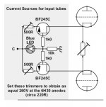
I assume that it must be a "differential" constant current sink like the one that Allen uses in his PP-2C - see attached image.
The schematic shows 2 single CCS'es, nothing differential about that...

The schematic shows 2 single CCS'es, nothing differential about that...
It's becoming differential through the common cathode resistor. As Allen has explained, trimming that resistor, controls the Gm degenaration of the cascoded tube, hence adjusting the gain of the stage.
When I was writing "differential" ccs, the term was in quotes, trying to describe this twin ccs acting as common ccs in a differential stage.
It cannot be differential in the sense of a LTP - and that is not its designed function. Its function is to keep the triode in Constant Current operation to maximise linearity.
Allen never really employed proper hard differential operation. In the case of his PP amp he said that proper differential operation compromised bass extention. Again this is one of those areas where I fundamentally disagree with Allen as I firmly believe in the LTP principle of hard differential stages.
Shoog
Last edited:
As far as I can see, in his preamplifiers (except RTP3D), Allen implemented true differential LTPs, with single CCS to both tubes, or both cascodes.
Back to my power supply
Hello
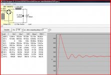
Back to the power supply. Here my firt simulation.
As you can see, very strong over shoot at 545V + instability.
Guys from VSE, says that will not be a problem with the VSE Superrreg I plan to use.
What do you think about this ? Will that be "listenable" (sorry for my english) ?
Sure I can add a resistance but that increase the time constant and reduce the output voltage.
Vincent
Hello
Back to the power supply. Here my firt simulation.
As you can see, very strong over shoot at 545V + instability.
Guys from VSE, says that will not be a problem with the VSE Superrreg I plan to use.
What do you think about this ? Will that be "listenable" (sorry for my english) ?
Sure I can add a resistance but that increase the time constant and reduce the output voltage.
Vincent
Attachments
Hello
Back to the power supply. Here my firt simulation.
As you can see, very strong over shoot at 545V + instability.
Guys from VSE, says that will not be a problem with the VSE Superrreg I plan to use.
What do you think about this ? Will that be "listenable" (sorry for my english) ?
Sure I can add a resistance but that increase the time constant and reduce the output voltage.
Vincent
Hi Vincent,
My PSU has the same values of 10H and 47uF, but I put a 2uF cap before the choke. I tuned the value of this cap to get a 350V output from a 300VAC secondary winding. I suspect that this will have much less overshoot than with your arrangement, but I haven't measured or simulated it.
Unfortunately adding the capacitor will increase the DC output voltage, so this would require you replacing (or rewinding) your power transformer...
Alex
Hi
Transformer is not buyed yet.
Adding a 2µ cap will reduce 1/2 the output ripple voltage (1,6V => 0,8V) (PSUD2 sim)
It will add a new time constant with the transfo resistance (36 Ohms) => 5tx = 0,36ms (much lower than the time constant Rchoke + 47µ => OK)
What was the reason to add this 2µ cap ?
vincent
Hi
Transformer is not buyed yet.
Adding a 2µ cap will reduce 1/2 the output ripple voltage (1,6V => 0,8V) (PSUD2 sim)
It will add a new time constant with the transfo resistance (36 Ohms) => 5tx = 0,36ms (much lower than the time constant Rchoke + 47µ => OK)
What was the reason to add this 2µ cap ?
vincent
Partly to add extra filtering, but mainly to tune the unregulated output voltage, as I couldn't use a simulator on my Mac 🙂
I would be interested to see your simulations! My guess is that the extra time constant is not really relevant to the performance of the PSU, since any resonance at this frequency on switch-on will be isolated by the choke and 47uF cap from the rest of the circuitry.
Alex
Hello
Back to the power supply. Here my firt simulation.
As you can see, very strong over shoot at 545V + instability.
Guys from VSE, says that will not be a problem with the VSE Superrreg I plan to use.
What do you think about this ? Will that be "listenable" (sorry for my english) ?
Sure I can add a resistance but that increase the time constant and reduce the output voltage.
Vincent
The overshoot is only at the moment of turn on.
It seems that about 120uF after the choke would be better than 47uF.
The Shunt Regulator will smoothen any residual ripple, so there should be no problem, neither with overshoot nor with ripple.
- Home
- Amplifiers
- Tubes / Valves
- Vacuum State RTP3C