Thanks for pointing it out. Not only that but some values are also different.
I realize now there seems to be different versions of this schematic. The question is which one is the most up-to-date. that would explain why your values are different than the ones I have.
I followed a good print which is the entire service manual. All values are easily readable. How can I send to you the schematic I have for comparison?
oh I see in fact I cannot see the value you mention in my schematic both the BBC and the Baton, you can attach your schematic here....thank you very much

Just checked the BBC schematic and it's definitely a typo in there and most likely the source of your problem.
C20 for 1280hz is 0.0033. C21 for 2560hz is roughly half of C20 which should be 0.0017 not 0.0161. Continuing the same formula for 5120hz C22 is half of C21 which is 853p.
If you used 0.0161 instead of 0.0017 it would probably give you the dip you're seeing at 2560hz. Don't forget that there is 2 of them C21 and C14.
thank you very much Dromichet you are absolutely right, I will modified the cap value and report the result, my email is ackyfr@icloud.com ....many thanks for your help...🙂
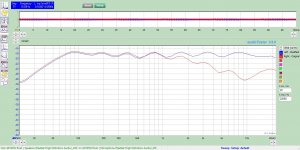
I played around with my build and modified some of the resistor values. I'm not an EE and I don't really know if these mods have any adverse effect. I only went by the better frequency response these mods created. Maybe you'd know if these mods should not be done.
The changes made based on the schematic I've send you with your schematic in brackets. The FR curves after these mods are attached with all settings at 0db.
R38(R44) - from 680K(560K) to 470K
R39(R45) - from 680K(560K) to 290K
R40(R46) - from 680K(560K) to 100K
R41(R48) - from 470K to 200K
The changes made based on the schematic I've send you with your schematic in brackets. The FR curves after these mods are attached with all settings at 0db.
R38(R44) - from 680K(560K) to 470K
R39(R45) - from 680K(560K) to 290K
R40(R46) - from 680K(560K) to 100K
R41(R48) - from 470K to 200K
Attachments
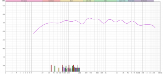
I received the schematic by email, wow so many differences on component value I cannot believe that I became mad on try to fix the dip but I could never ever imagine was a mistake on the schematic print just a dot on the wrong place.....I changed the two cap from 16.1nF to 1.7nF and boom problem solved, you really are the one solve the problem thank you so much, I think the schematic you have is a review from the original, I saw as you point out so many other differences from the previous but I am not bother to change all component that are not so influential.
Also you get a very good result now, the resistors you change value are ok, they are just attenuating the signal before going to the pot so if you get that result just keep it as it is....all the best
Also you get a very good result now, the resistors you change value are ok, they are just attenuating the signal before going to the pot so if you get that result just keep it as it is....all the best
Attachments
Yes that's true, by the way I find other schematic, I think on 1959 when this product come out in the market was a really big innovation so has been modified for different application, I even find a version with pickup input for guitar, and 62 years later we still appreciate it, by the way I have different modern 31 band EQ but what the Baton do to music still amazing me, really love it....all the best
Attachments

I am going to put the 12AX7 differential amp in post #6 into a Realistic 31 8000 eq.
Should be relatively painless and offer most of the tube flavor.
Should be relatively painless and offer most of the tube flavor.
Hi stocktrader200 can you be more specific in your message, post #6 where? .....all the bestI am going to put the 12AX7 differential amp in post #6 into a Realistic 31 8000 eq.
Should be relatively painless and offer most of the tube flavor.
The pdf file shows a 12ax7 as the gain stage differentially connected. It has 2 100k resistors on each plate and both cathodes connected together and fed by a 110k resistor. A buffer will replace the 12au7 allowing it to be plugged in to the circuit
Oh I see, yes good idea should work ok ....all the bestThe pdf file shows a 12ax7 as the gain stage differentially connected. It has 2 100k resistors on each plate and both cathodes connected together and fed by a 110k resistor. A buffer will replace the 12au7 allowing it to be plugged in to the circuit
Of all the EQ schematics I've seen using the split-load/cathodyne/concertina circuit, that's the only one I saw with tapped pots. Not sure they are even necessary. The split-load style uses way less tubes and is much simpler. The only hitch is to find suitable chokes in the EQ network..."That Fender circuit looks interesting. Apparently it requires tapped pots. Are those even made anymore?"

Here are four solid state ones from another post in the "analog line level" forum, none used tapped pots. I believed they can be appropriated into tube circuits.


12AX7 could replace the JFET in schematic #2
R2 and R7 changed to 4.7k
Signal input should always be referenced to GND instead of the negative rail.
R2 and R7 changed to 4.7k
Signal input should always be referenced to GND instead of the negative rail.
Last edited:
Concerning the 2nd schematic :
±40V supplies are more than a little too high for a circuit using 2N3819's -- their max voltage is around 25V. Sooner or later a mated I/O, or power supply sequence will damage one.
A 12AX7 would be a huge redesign -- very different behavior from an FET-Sziklai-pair. Plus two more, much-higher-voltage power supplies!
Also, I wouldn't personally waste the front panel space, the linear pot expense, OR THE COIL-winding time, effort, and expense, on 15Hz or 25kHz bands. Only the band edges will be audible; if you're running vinyl, rumble will get a huge boost before any useful audible boost occurs; tweeters have been smoked despite a total lack of any audible indication.
40Hz and 16kHz, on the other hand, would be eminently useful.
Cheers
Dear kissabout2002, could you send me this high quality pdf to me please? my email is opacheco_hn@yahoo.comYes that's true, by the way I find other schematic, I think on 1959 when this product come out in the market was a really big innovation so has been modified for different application, I even find a version with pickup input for guitar, and 62 years later we still appreciate it, by the way I have different modern 31 band EQ but what the Baton do to music still amazing me, really love it....all the best
Thanks anticipated
opacheco

- Home
- Amplifiers
- Tubes / Valves
- Vaccum tube Equalizer schematic?