Ok Sajti,try it then share.And the PSU, and the housekeeping PSU gerbers too
I will share them, if anybody interesting. I just made some minor changes on the amplifier, and the PSU pcb. I want to try them before share
Sajti
This will be the first step if you want followers.
")
Thimios
I didn't phrase my question very well. Let me try again. You're using a simple current mirror with T23 and T24 rather than the more usual three transistor Wilson current mirror. I guess my question is does this make a noticeable difference?
I did it in the 1st version, but there was no difference in the simulation, and finally no difference in practice. The open loop gain is same with the 2 solution.
Sajti
This will be the first step if you want followers
Getting followers is not my first target. I just want to build better and better amplifiers. I can share my results if anybody interesting in it.
Sajti
Thanks, good to know about the mirrors. A couple more questions if I may. Firstly what is the benefit of operating the input stage at near saturation? Secondly have you made any distortion measurements on the finished amplifier? I ask the latter question because it seems straightforward enough to get less than 10ppm simulated distortion with a CFA but the measured results always seem to be higher. Seems to be easier to build a "conventional" VFA if you want to get low measured distortion?
Yet another question. I have seen CFA designs where the mirrors operate at a 1:1 current ratio but the input diamond transistors operate at a 1:3 ratio ( T31=1mA, T29=3mA ). This doesn't strike me as a good idea, and will probably lead to higher distortion, but I have neither built nor simlated this so I don't know for sure. Any ideas?
Firstly what is the benefit of operating the input stage at near saturation?
Not the Vce voltage is the most important, but the bootstrapping. There working point is almost constant, and the dissipation of the 4 input device is close to each other. Another advantage, that the internal capacitances are not change, if You drive the amplifier. Anyway I'm thinking to use LED instead of 1N4148 in the input stage, which increase the Vce with 1V.
Secondly have you made any distortion measurements on the finished amplifier? I ask the latter question because it seems straightforward enough to get less than 10ppm simulated distortion with a CFA but the measured results always seem to be higher. Seems to be easier to build a "conventional" VFA if you want to get low measured distortion?
I try, but I failed with it, as my HP distortion meter is not able to measure below 0,05%, and the amplifier produces lower distortion. I have to find better equipment..
Sajti
Yet another question. I have seen CFA designs where the mirrors operate at a 1:1 current ratio but the input diamond transistors operate at a 1:3 ratio ( T31=1mA, T29=3mA ). This doesn't strike me as a good idea, and will probably lead to higher distortion, but I have neither built nor simlated this so I don't know for sure. Any ideas?
I didn't try that, but I will simulate it, as I'm curious about the result.
Sajti
metalwork nitpicker like me.
Same for me. Now I changed the pcbs, to reduce the metalwork. I have to drill much less holes with that...
Sajti
Hi
What are the simulated THD results for this amp?
Hi,
0.0008% at 1kHz, 8ohm load, and 32V output.
Sajti
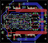
Input directly near high current outputs?
BR, Toni
Yes. My experience, that the shortest feedback route is very important. Anyway it's not so close, if You check, and there is the GND route between them.
Sajti
In my experience the length of the feedback path is not as important as a noise/EMI free return path. My high performance SA2014 power amplifier has a feedback path of about 30 - 40 cm length...
I'm not as smart to tell, that Your point of view is bad. I believe another one: There can be distortion or noise if the feedback path is long. I take the feedback signal from directly the output point, and keep the route short.
Yes I did. My AC voltmeter has the most sensitive setting is the 10mV maximum. I try it, and the result was somewhere around 0.4-0.5mV. There was no audible noise with my ear 1cm away from a 104dB/W/m loudspeaker.Have you measured noise in the ready made amplifier?
Sajti
I haven't said that a short feedback path is bad nor that a longer feedback path is better ...
Maybe I should say: "Input directly near big lytics?" instead of "Input directly near high current outputs?"
Just for comparison to show that not the length of the feedback path may be a problem:
Maybe I should say: "Input directly near big lytics?" instead of "Input directly near high current outputs?"
Just for comparison to show that not the length of the feedback path may be a problem:
- SA2014 with 8pairs output devices and with it's long feedback path has a wideband noise of 117µV
- SA2015 with one pair of output devices and ultra short feedback path has a wideband noise of 137µV.
Last edited:
Maybe I should say: "Input directly near big lytics?" instead of "Input directly near high current outputs?"
That capacitors has no big current spikes, as they are for the driver psu decoupling, and the feedback decoupling.
Just for comparison to show that not the length of the feedback path may be a problem:
- SA2014 with 8pairs output devices and with it's long feedback path has a wideband noise of 117µV
- SA2015 with one pair of output devices and ultra short feedback path has a wideband noise of 137µV.
The lenght of the feedback path is the only difference? I mean that this is negligible amount of noise, and many things can change the result.
Sajti
- Home
- Amplifiers
- Solid State
- V6 amplifier