I amn't sure about the better solution.Your way make me feel a little bit embarrassment when you said connecting Speaker GND back to power supply better than connect to power amp board. However, many commercial expensive amp that are also use same as it.
All my test say that power supply gnd is much better but i haven't the oportunity for an isolated input generator.
I always use my p.c sound card when testing.
This way,inp gnd and out gnd aren't insulated,may be this affect the results.

Sajti,
assuming that V6 relates to the number of output devices, your last design ain't no V6 any more, is it? It rather should be christened V4, shouldn't it?
Resembles somewhat the downsizing in cars' engines. Anyway, a very clever design
Best regards!
Yes it's something like downsizing
But V6 is still in development, and I'm working on V8 as well Sajti
This way,inp gnd and out gnd aren't insulated,may be this affect the results.
The whole GND is more or less floating if no input connected. There is only 100ohms+100nF+double diode network connecting it to the safety ground. I usually do it with dual mono psu.
I use different solution if there is common PSU for the 2 channels.
Sajti
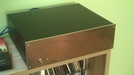
Congratulations!
Very neat chassis..
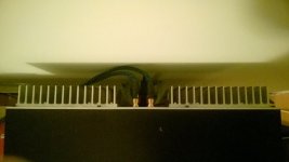
Thank You. I like the old style amplifiers with heatsinks located on the back. This is, why I build my amplifier like this.
Sajti
On looking at your pic I suspected that there weren't any sinks at all!
Best regards!
I think that the protection would shut down the amplifier even without any input level...
Sajti
Could I ask why you have T24 rather than T23 diode connected in your schematic in post #32. Most cfb amps which use a topology similar to yours have T23 diode connected. Whilst your design obviously works, are you not throwing away open loop gain by having such a low impedance load ( effectively a 470R resistor ) for T27? If this is the case then will the distortion be higher than it needs to be? Or maybe I'm missing something - happens a lot at my age!
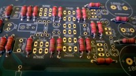
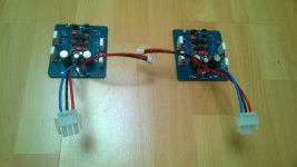
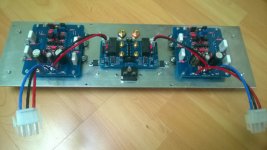
Nice work Sajti!Here is the picture of the pcb.
There are some minor changes, as I had many BC327, so I use them instead of BC516. Works very well, only 0,1V loss on it... All values are on the pcb to easy implementation. Output relay is Omron G2RL2 12V coil version.
The pcb is Pcbway friendly designed. You can get 10pcs. for 5USD+delivery. Gerber is available if You need.
This pcb has connection to the housekeeping psu pcb, which contains small EI tansformer, and inrush current limiter, driven by the turn on delay circuit.
Sajti
Yes i need gerbers
Last edited:
Just post amplifiers gerbers if you want to share a full project.
And the PSU, and the housekeeping PSU gerbers too
I will share them, if anybody interesting. I just made some minor changes on the amplifier, and the PSU pcb. I want to try them before share
Sajti
- Home
- Amplifiers
- Solid State
- V6 amplifier