For a standard F5, use (4) 0.47R 3W per rail.
Bleeder can be anything from 2.2K to 5K 3W, it is not a critical value. If you need to order something use 2.2k 3W,
Bleeder can be anything from 2.2K to 5K 3W, it is not a critical value. If you need to order something use 2.2k 3W,
I’m also looking for a suggestion on the input snubber values. I don’t have access to a scope. I understand the input snubber values depend on the used transformer and will be hard to recommend without measurements.
I’m using an Amplimo (toroidal transformer) 500VA Pri:230V sec 2x18v, for a F5 build. Would it be possible to suggest a ball park figure for RS1&RS2, CX1&2, CS1&2, or is this not recommended?
I’m using an Amplimo (toroidal transformer) 500VA Pri:230V sec 2x18v, for a F5 build. Would it be possible to suggest a ball park figure for RS1&RS2, CX1&2, CS1&2, or is this not recommended?
Not really. The BOM attached to post #1 says this:I believe the suggested values [of RS1&RS2, CX1&2, CS1&2] are on the BOM.
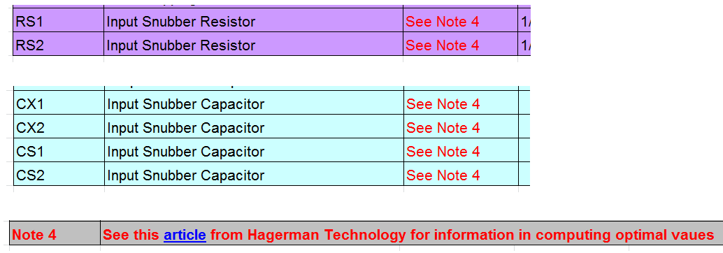
Hagerman's article (LINK) is many pages long but the central result is a single equation, found on page 4:
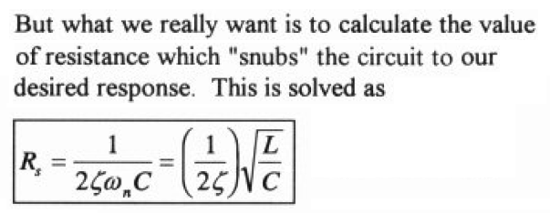
The squiggle next to the numeral "2" is the lowercase Greek letter "zeta", which is the damping factor of the resonant circuit. "L" is the secondary leakage inductance of the power transformer, measured with primary shorted. "C" is the sum total of transformer secondary capacitance, plus rectifier capacitance, plus across-the-secondary capacitor Cx (if fitted).
Hagerman suggests measurement procedures to find L and Ctransformer and Crectifier; naturally they involve measurement equipment. "Quasimodo" on the diyAudio website suggests design-and-measurement procedures; naturally the measurement procedures involve equipment, specifically an oscilloscope.
When measurement is impossible or untrustworthy, it may be tempting to use a guess or a "ballpark figure" instead. In a CRC snubber such as the one laid out on this PCB, the designer can choose Cx to be much much greater than Ctransformer + Crectifier. Then all but one of the variables in Hagerman's equation are known: (zeta = 1.00 (gives "critical damping")) and C = Cx. If you have a guess or an estimate of secondary leakage inductance L, you can calculate an appropriate snubber resistance Rs.
How do you guess the value of your secondary leakage inductance L without making any measurements? I don't know. (That's why I use a Quasimodo; I prefer to measure rather than to guess. But I own an oscilloscope.) I suppose you could ask somebody else to make the guess for you; then if your design fails, it's their fault not yours. I suppose you could collect measured secondary leakage inductance numbers from other people, and use some kind of data manipulation technique to combine them into an "informed guess."
Attachments


As the article also suggests, the wrong values can make things worse. That's why I prefer to leave out the snubber, and my amps sound great. I will eventually have to make a quasimodo to measure and try out a proper snubber, but I have other priorities at the moment.
Thanks Mark, very thorough. 🙂 I guess most previous builds didn't have this input snubber and it's optional, so no big issue. I'm just trying to go all out on this build.
I might put the question to Amplimo, see what they say.
I might put the question to Amplimo, see what they say.
One last question (famous last words). Which way around do I connect the secondairy windings to the PSU, ie looking at these pictures which colour goes to AC1A, AC1B, AC2A &AC2B. I take it as long as the same winding pairs are connected on the same side. However does the "top" of the windings go to the "A" and the bottom to the "B" sides?
What would you suggest?
What would you suggest?
An externally hosted image should be here but it was not working when we last tested it.
An externally hosted image should be here but it was not working when we last tested it.
Last edited:
Yes as long as the same pair is connected on the same side it should be ok.
I'd wire it like this
AC1A-Red
AC1B-Yellow
AC2A-Blue
AC2B-Grey
HTH
I'd wire it like this
AC1A-Red
AC1B-Yellow
AC2A-Blue
AC2B-Grey
HTH
Hi All
I have searched this thread, and, looked at Digi-Key, Mouser and Newark
I cannot find many options for values over 10,000uf with 10mm lead spacing.
What are you guys using ?
I have searched this thread, and, looked at Digi-Key, Mouser and Newark
I cannot find many options for values over 10,000uf with 10mm lead spacing.
What are you guys using ?
What voltage do you want?
Also you need to search for 10mm, snap-in, radial pins.
Limit yourself to Panasonic and Nichicon, they are both the best quality, and removes a ridiculous amount of noise from the search parameters.
Also you need to search for 10mm, snap-in, radial pins.
Limit yourself to Panasonic and Nichicon, they are both the best quality, and removes a ridiculous amount of noise from the search parameters.
Elna Silmic II probably sounds better if I may believe this High End Audio - Electrolytic capacitors
I am coming to a conclusion that the better the "on board decoupling" the less the main smoothing affects the upper frequency audio performance. Bass still needs adequate current supply from the PSU.
Has anyone got evidence that this might be the case?
Has anyone got evidence that this might be the case?
Elna Silmic II probably sounds better if I may believe this
Regardless of the Silmic performance, (which is outstanding) it doesn't matter for a PSU - the values needed for a PSU are an order of magnitude bigger than the largest Silmic.
What voltage do you want?
Also you need to search for 10mm, snap-in, radial pins.
Limit yourself to Panasonic and Nichicon, they are both the best quality, and removes a ridiculous amount of noise from the search parameters.
I'm looking for 80 volts, which seems to be the issue.
There are lots of options in the less than 63vdc range.
I have purchased from mouser, digi, and newark many times before, for personal and professional applications, so very familier with specifing and searching their inventories.
Also, bought from boutique cap suppliers before as well, but getting large value 80v caps to fit the V3 UPS board seems problematic.
Looks like I will need to modify the board or just build a board from scratch.
A few months ago Newark had 22,000 µF 10 mm snap-in 35 mm dia Nichicon caps. I can't find them now. Mouser had 10,000 µF Panasonics that it doesn't seem to stock anymore. I guess the market is heading towards low voltage applications. Bummer for those of us looking to build high capacitance filters at 80V or better.
OOPS, found the 22,000 µF caps, they are 40 mm diameter to fit another PSU board I have. The unit price has gone up $10 to $36. Ouch.
OOPS, found the 22,000 µF caps, they are 40 mm diameter to fit another PSU board I have. The unit price has gone up $10 to $36. Ouch.
Last edited:
A few months ago Newark had 22,000 µF 10 mm snap-in 35 mm dia Nichicon caps. I can't find them now. Mouser had 10,000 µF Panasonics that it doesn't seem to stock anymore. I guess the market is heading towards low voltage applications. Bummer for those of us looking to build high capacitance filters at 80V or better.
Or the market is heading towards 4 -5 pin types for better mechanical stability of the larger can sizes.
There was a lot of choices in large sizes, just not 2 lead - 10mm lead spacing.
- Home
- The diyAudio Store
- V3 Universal Power Supply Circuit Board