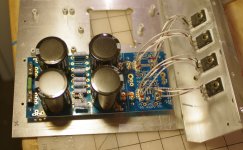
The reorder went out to fabrication yesterday, I think...
Does this mean week/two, or more?
For those who wish to install snubbers (schematic components CX1, RS1, CS1) into this PCB, but find the mathematics and measurements of Jim Hagerman's article to be a bit daunting, may I suggest http://www.diyaudio.com/forums/powe...sformer-snubber-using-quasimodo-test-jig.html. You attach this little jig to your transformer, connect up an oscilloscope, and 3 minutes later you've got an optimum (criticaly damped, zeta=1.0) snubber, without ever picking up a calculator or launching a spreadsheet.
Since the optimum component values of this type of snubber depend upon the power transormer and nothing else, we can make a table of transformers and their optimized snubbers, so that folks don't need to reinvent the wheel. To show an example, I will provide one entry for this table:
Transformer: Avel Lindberg Y236602
type: toroid, dual primary (115/115), dual secondary (35/35)
size: 230 VA
configuration used here: primaries parallel (115V), secondaries series (70V)
application: Akitika GT-101 power amp
Optimized CX: 10 nF (0.01 uF)
Optimized CS: 150 nF (0.15 uF)
Optimized RS: 110 ohms
(Here's a link to the thread about AL toroid snubber)
Lead spacing for Input snubbers ?
As we are waiting for the boards to get made, could you kindly let us know the lead spacing for the input snubber, i.e. Cx and Cs ?
TIA,
Max
As we are waiting for the boards to get made, could you kindly let us know the lead spacing for the input snubber, i.e. Cx and Cs ?
TIA,
Max
As we are waiting for the boards to get made, could you kindly let us know the lead spacing for the input snubber, i.e. Cx and Cs ?
TIA,
Max
Cs - fits 2.5mm or 5mm lead spacing caps
Cx - fits 5mm or 7mm lead spacing caps
C17/18 - fits 5mm lead spacing caps
How should you use Rs, Cs if you are using heatsinks for diodes in TO-247 case? They just do not fit... underneath?
How should you use Rs, Cs if you are using heatsinks for diodes in TO-247 case? They just do not fit... underneath?
Everything should fit if you use the recommended heatsink outline, even for TO-247 packages. Though fitting it (Rs, Cs) underneath can also be a solution if you provide enough clearance with your stand offs.
There is probably room on top with the heatsink installed... However underneath would be fine as well.
I haven't fited it yet, but my first impression was — no way it will fit. I will find out something, we are DIYers here! 🙂
Cs - fits 2.5mm or 5mm lead spacing caps
Cx - fits 5mm or 7mm lead spacing caps
C17/18 - fits 5mm lead spacing caps
Thanks! Your help is highly appreciated!
I need some help soldering these big pads - can anyone point me to something that might help me get the hang of it? First time I have ever soldered these big 3w resistors and I can't get a clean joint. Using Cardas quad eutectic solder and iron set at 300 C. Do I need to heat these pads for a *serious* amount of time?
Personally I have my iron set to 380c.
The problem arises when there are fat tracks that 'leech' the heat away from the joint. Hotter and shorter time in this case.
The problem arises when there are fat tracks that 'leech' the heat away from the joint. Hotter and shorter time in this case.
UKToecutter (nice name btw 🙂 ) is correct...any pcb with huge tracks sucks the heat away. I would look at a higher temp (I have mine around 350 for usual stuff and maybe 380 for bigger tracks and parts) and a bigger iron.
size matters
You'll need a big chisel tip, maybe 3mm. The tiny ones don't carry the heat.
After a while you'll get used to bigger tips and higher heat. Now I am loath to shift gears down to the little stuff. Some say it is safer for your components to use higher heat for shorter durations; sort of searing the tips instead of toasting the whole component.

- Home
- The diyAudio Store
- V3 Universal Power Supply Circuit Board
