If I'm not mistaken, the comparison was made between the uTracer results and results obtained from a different curve tracer, both using the same bogey tube.The reason the uTracer results don't match a bogey tube curve is because such a tube does not exist. The curve is the average of many, perhaps even hundreds or thousands of tubes. Testing multiple tubes on the uTracer shows this very clearly - and the results are quite repeatable over time and instance.
So if they don't match, it is due to differences in how the measurements were taken, not because different tube samples were used.
If I'm not mistaken, the comparison was made between the uTracer results and results obtained from a different curve tracer, both using the same bogey tube.
So if they don't match, it is due to differences in how the measurements were taken, not because different tube samples were used.
You are right, the curves were based on a bogey tube, but the reviewer also mentioned the reason for the deviations were due to uTracer's calibration.
The biggest issue I see with this approach has nothing to do with engineering. The technical issues are primarily with the transformer. Low leakage inductance in a pulse transformer can be overcome by bi-filar or tri-filar winding. The isolation voltage will be an issue here as there should be better than twice the operating voltage in isolation between windings.
This means an expensive transformer as it will be in low volume.
This means an expensive transformer as it will be in low volume.
The only caveat, is these results are obtained with an external power supply for the heater. The internal heater yields between 3-8% lower results,
The heater voltage is best measured with a true, true-RMS meter. I found it to be off by almost 10%
I've asked that it be possible to scale one of the high voltages as a percent of the anode voltage so that ultralinear curves can be drawn.
It's simply not a good approach for a number of reasons.The biggest issue I see with this approach has nothing to do with engineering. The technical issues are primarily with the transformer. Low leakage inductance in a pulse transformer can be overcome by bi-filar or tri-filar winding. The isolation voltage will be an issue here as there should be better than twice the operating voltage in isolation between windings.
This means an expensive transformer as it will be in low volume.
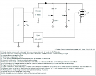
After giving the issues some thought, I've come up with a wonderful solution that is simple, cheap, reliable, and accurate. Once I draw up a basic diagram I'll post the idea. All that be required is a couple changes to the v3 design, and the firmware. No transformer and no HV switch required.
I hadn't read far enough into the V4 design to see that he is using off the shelf step down transformers in reverse. These will have uncontrolled leakage inductance.
While using off the shelf transformers solves the cost issue, and he may be able to design with the one he has chosen, if the manufacturer makes any changes in construction it could easily require a redesign of the circuit.
It would be best if he could find two manufacturers of the same transformer and insure it works with both.
Poynt99, I look forward to seeing your suggestion.
i had suggested the HV amplifier from Horowitz and Hill -- just 2 HV MOSFETs -- can be driven with a DAC or ramp generator -- and it doesn't burn a lot of energy, and it compensates rather easily. No sparks either.
OK, here are my suggestions for improvements to the uTracer design, in a basic form.
But first, R. Dekker deserves a lot of credit for his design. Obviously he has spent a great deal of time and effort in developing the uTracer.
See the attached diagram and basic description.
But first, R. Dekker deserves a lot of credit for his design. Obviously he has spent a great deal of time and effort in developing the uTracer.
See the attached diagram and basic description.
Attachments
But first, R. Dekker deserves a lot of credit for his design.
Amen to that!
Have you thought of emailing Ronald directly? He's extremely approachable and welcomes input from interested parties.
The problem with the heater supply is largely due to inductance - the software assumes its a square wave and calculates the power & effective DC voltage from the mark/space ratio and supply voltage (about 19V, which is accurately measured at run time).
In practice, the heater waveform is nothing like a square wave due to circuitry & wiring inductances, and this leads to the heater issues - Ronald is well aware of this and its one of the things that will be fixed in V4.
The V4 blog documents a "work in progress" - he is a serious professional engineer and this is a labour of love - in real terms, I suspect it costs him money - the blog is a fascinating read as its presented more like lecture notes (he is, after all, a professor at TUe).
Last edited:
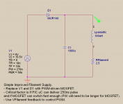
IMO, a far better approach for the filament supply would be to filter the pulsed output.
The benefits include the following:
1) Parasitic inductance from wiring etc. becomes a non-issue.
2) The filtered output can easily be measured by the PIC uC in order that the PWM be set to achieve the specified filament voltage.
3) The modification is simple.
4) The current flowing in the filament will be smoother and less likely to cause adverse effects in the measurements.
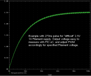
The only caveat to achieve such low filament voltages such as for a 2.5V/1A filament, the PIC uC must be able to output a 270ns pulse (probably longer considering the MOSFET will require some turn-on time).
See attached schematic and simulation results.
I'll try and contact Ron directly to offer my suggestions.
The benefits include the following:
1) Parasitic inductance from wiring etc. becomes a non-issue.
2) The filtered output can easily be measured by the PIC uC in order that the PWM be set to achieve the specified filament voltage.
3) The modification is simple.
4) The current flowing in the filament will be smoother and less likely to cause adverse effects in the measurements.
The only caveat to achieve such low filament voltages such as for a 2.5V/1A filament, the PIC uC must be able to output a 270ns pulse (probably longer considering the MOSFET will require some turn-on time).
See attached schematic and simulation results.
I'll try and contact Ron directly to offer my suggestions.
Attachments
The above idea is good if there is an easy way to implement the switch (there isn't one I can see).
However as Ron has suggested in his blog, I concur that a good approach would be to utilize a proper buck converter circuit. But I would suggest that the output be measured and PW controlled to achieve the specified filament voltage.
However as Ron has suggested in his blog, I concur that a good approach would be to utilize a proper buck converter circuit. But I would suggest that the output be measured and PW controlled to achieve the specified filament voltage.
Why not include a low cost RMS to DC converter like the one below, then measure the DC level through one of the unused ADC inputs of the PIC. The loop control on the heater supply does not need to be a state of the art one.
http://www.analog.com/static/imported-files/data_sheets/AD737.pdf
http://www.analog.com/static/imported-files/data_sheets/AD737.pdf
I don´t think there is even the need for the PGA. The maximum Vheater(RMS) that can in theory be obtained from the internal supply must be less than 19v, but more typically 15v. If the output of the converter is scaled down 10:1 by a resistor divider, then voltages to be measured by the PIC´s ADC would range from 0.25 to 1.5v. That´s perfect for the PIC, plus the 10bit resolution would allow for a more than good enough voltage regulation.
I've contacted Ronald a few times via email, but nothing much came out of it. He does not seem to think the ideas I presented are doable.
So, is the V. 3 good enough for ordinary octal, 9 pin and 7 pin miniature tubes? I don't plan on testing DHT's or exotic tubes.
So, is the V. 3 good enough for ordinary octal, 9 pin and 7 pin miniature tubes? I don't plan on testing DHT's or exotic tubes.
The V3 is fine with all the above -- but you have to wire it up to various sockets -- i used miniature banana jacks -- you could also purchase a used tester with switches but would have to deal with a lot of stray inductance.
The V3 is fine with all the above -- but you have to wire it up to various sockets -- i used miniature banana jacks -- you could also purchase a used tester with switches but would have to deal with a lot of stray inductance.
OK, thanks.
I realize that I need one socket of each type, but you believe that banana jacks are better for performance than rotary switches? I have not read the construction manual so pardon my ignorance.
- Home
- Design & Build
- Equipment & Tools
- uTracer...