UTHAiM as IV Converter
Something reminded me of the current convey nature of the UTHAiM.
So how about using it as an IV Converter ?
The Spice files show an IV using a current out DAC at 1mA and Vref=0, as an example.
Output is set by Riv (R3) to 2Vrms.
It is deliberately shown without Civ, in order to make the bandwidth of the circuit itself visible.
So the Civ show be added accordingly.
The output at R3 (Out1) is practically distortion free.
If the load is 10k or above, you can skip the lateral FETs and just use a JFET follower as buffer (e.g. 2x 2SK170BL).
But you can also attach a 300~600R headamp directly to the MOSFET output.
And you can simply use a switched resistor pot for R3 as volume control.
So much fun, 😉
Patrick
.
Attachments
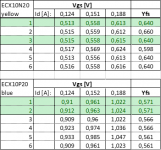
A little progress after quite a while. I received the Exicon ECX lateral FETs yesterday and now I got them measured according to EUVL's instructions in post #39. I have attached my measurement results and marked with green color the ones that I chose to be used in my build.
So the next step will be according to my understanding to calculate the values for R21 and R21 as shown in the guide in the first post:
R21 = (Vgs_ECX10N20 + R31 x I_bias) / Idss_JFET = (0,558 V + 0) / 8,2 mA = 68 ohm
I suppose I can leave out the R31 and replace it with a jumper? I don't have a scope for measuring the second harmonics. 🙄
R22 = (Vgs_ECX10P20) / Idss_JFET = 0,961 V / 8,2 mA = 117 ohm
So I choose closest standard value resistor and then trim them by minimizing the DC offset. I hope I got all of this right...
Attachments
I assume you already have matched JFETs and you have measured their Idss to be exactly 8.2mA ?
If so the numbers above looks OK.
You can jumper R31.
The Exicon's have more similar Yfs than the Renesas.
Patrick
If so the numbers above looks OK.
You can jumper R31.
The Exicon's have more similar Yfs than the Renesas.
Patrick
Let's use Morde's data as an exercise.
In this particular case, the P channel has a higher Yfs than the N channel.
The difference in 1/Yfs is 0.19 ohm.
So if we wish to have equal AC current sharing between the two MOSFETs, R31 should be ~0.19ohm, and assigned to the P-channel.
That means e.g. 3x 0.56ohm in parallel (e.g. Mouser 279-LR1LJR56).
And J22 should be shorted instead of J21.
R21 = (Vgs_ECX10N20) / Idss_JFET = 0.558V / 8.2 mA = 68 ohm
R22 = (Vgs_ECX10P20 + R31 x I_bias) / Idss_JFET = (0.961V +0.19*0.15) / 8,2 mA = 121 ohm
Patrick
Kudos to Patrick again for these enlightening examples! I will adjust my boards accordingly.
Yes, my JFETs are matched and the Idss = 8,2 mA when using a 2,5 ohm source resistor. This is according to forum user liubincalvin from whom I bought the JFETs.
Yes, my JFETs are matched and the Idss = 8,2 mA when using a 2,5 ohm source resistor. This is according to forum user liubincalvin from whom I bought the JFETs.
BTW I suggest you use a piece of copper wire to short J22.
It has to pass ~300mA at full current swing.
Patrick
It has to pass ~300mA at full current swing.
Patrick
I'm using Audeze LCD 2.2F (Fazor) headphones. They are quite sensitive (101dB/mW) and have a static impedance of 70 ohm throughout the frequency range. Possibly I will aquire a pair of Sennheiser HD800S phones too at some point - after I rob a bank. =)
I'll use a piece of wire for J22. Or is it actually J32 as it reads on my boards?
I'll use a piece of wire for J22. Or is it actually J32 as it reads on my boards?
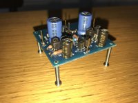
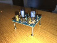
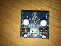
I think I have some problems while testing the front end without the lateral FETs. I measure 6,9 V across R7/R8 and 0V across R5/R6. The voltage across R11 is 12,6 V. I suppose there's something wrong with the positive voltage side of the boards. The error is systematic as it is present in both boards. Rail voltages are +-23,4 V.
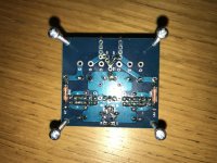
Any help with error finding is highly appreciated! I attached few pictures of one board if it helps.
Any help with error finding is highly appreciated! I attached few pictures of one board if it helps.
Attachments
Last edited:
Before you do anything, please clean off all the flux residuals with a PCB cleaner.
Did you short the input to Gnd during test ?
What are the voltages across the 4x 499R at the front end ?
They should be 499R x 8.2mA = 4.1V, all 4 of them, if the current mirrors are working properly.
Patrick
Did you short the input to Gnd during test ?
What are the voltages across the 4x 499R at the front end ?
They should be 499R x 8.2mA = 4.1V, all 4 of them, if the current mirrors are working properly.
Patrick
Ok, will do the clean up. 😱
I shorted the input to ground and I did expect the voltages to be 4,1 V but they were not. I'll try to test again tonight, if not, then it will be next week. Thanks for all the help!
I shorted the input to ground and I did expect the voltages to be 4,1 V but they were not. I'll try to test again tonight, if not, then it will be next week. Thanks for all the help!
All is good. I had accidentally connected the input somewhere else than ground. 
Now I get 0,11 V and 0,13 V across the R11. This looks reasonable and I can continue by tweaking the DC offset closer to zero. Voltages across the 499R resistors were 4,2-4,3V.
Now I get 0,11 V and 0,13 V across the R11. This looks reasonable and I can continue by tweaking the DC offset closer to zero. Voltages across the 499R resistors were 4,2-4,3V.
Still, clean the board until there is no fluke residual left.
soldering - Why do we need to remove flux from circuit boards? - Electrical Engineering Stack Exchange
Patrick
soldering - Why do we need to remove flux from circuit boards? - Electrical Engineering Stack Exchange
Patrick
Jeah, I did clean the boards with IPA before I gave it another try. Interesting reading behind the link. I didn't know that the flux can be conductive.
If the PCB surface does not feel smooth and slippery on the finger, then you still have residual.
Someone complained about bias stability of the F5-HA.
Turns out he did not clean the PCB properly.
Patrick
Someone complained about bias stability of the F5-HA.
Turns out he did not clean the PCB properly.
Patrick
I have now one channel's front end DC balanced. Voltage across R11 goes from -17 mV at starting point to hovering 0...-4 mV after 15 min. I suppose it is normal for the voltage to move a bit? I hope this is a good enough result.
Next I will have to wait for a couple of reistors to arrive so I can continue with second channel's front end and after that the output DC balancing. Should I have the input shorted to ground when I trim the output DC offset?
Next I will have to wait for a couple of reistors to arrive so I can continue with second channel's front end and after that the output DC balancing. Should I have the input shorted to ground when I trim the output DC offset?
> I suppose it is normal for the voltage to move a bit?
Yes. Anything below 30mV is good result.
> Should I have the input shorted to ground when I trim the output DC offset?
Of course.
Patrick
Yes. Anything below 30mV is good result.
> Should I have the input shorted to ground when I trim the output DC offset?
Of course.
Patrick
- Home
- Amplifiers
- Headphone Systems
- UTHAiM -- Just for Fun