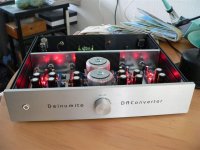
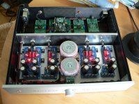
I removed the caps and now the smps seem happy...
Is my math right here?
49v input
2.35v across the 10 ohm resistor
1.4v across the 220ohm
output is 5.97v
current = 235 ma
Base voltage is 5.97 - 1.4 = 4.57
Target voltage is 30v, so 30v - 4.57v = 25.43v
25.43v/235ma = 108ohm
I tried a 110ohm resistor in place of the 220 and I'm getting only 5.3v output
I put a 5.1k resistor in and I get 37v, so I'm guessing I moved a decimal place somewhere...
You used the main CCS current in your math where you should have used the 1.4V/220R. You need 3.99K. Parallel circa 20K something to the 5.1K to get in the ballpark.
hi, i use Mezmerize to output +-15v, i got -13.8v and +25.2v
how can i fix?
Parts:
Tx: 2x18v 80VA
R1: 2x 47r both side, voltage across (0.23/2.13)
Voltage setting: 2 leds + 1.5Kr ( voltage across (13.8 / 24.6)
heat at IRFP240 but cold at IRFP9240.
how can i fix?
Parts:
Tx: 2x18v 80VA
R1: 2x 47r both side, voltage across (0.23/2.13)
Voltage setting: 2 leds + 1.5Kr ( voltage across (13.8 / 24.6)
heat at IRFP240 but cold at IRFP9240.
Start changing transistors on the bad side. First bjt, check. Then jfets, check. Last, Mosfets. Add a liittle more resistance on the good 13.8V side to go 15V your target.
Check all connections are as good as the ones on working side. Be sure you have right polarity Mosfets on bad side.
problem solved.
when flip all SK170 on the pos side and one must do the bend "middle leg" trick, i get the voltage drop finally, then i remember it is some where on the instruction at 1st page...
Another question:
I follow the positive schematic to made another PSU for powering a t-amp and get the 13.8v output without problem, with 225VA 2x18V Tx, i hope to get about 2.5A, so put 1.8//1.8 10W resistor in R1
i found the resistors is quite hot to touch, is this normal?
Good news, there is always a reason for a fault, takes care. Yes its normal your resistor(s) will burn enough power, 1.7-2V*2-2.5A. Choose it 3 times more powerful than what it consumes and keep it high off board.
Hi Salas,
I'm using half of an old Mez board to make a 5v supply for one of those LDR volume control thingumys.
I have 11.2v AC supply tap from my transformer.
Almost all of the components in place like in your first post.
I'm not hot-rodding obviously (4x leds is about as low a power requirement as you can get), so I'm using 2x68 for the current set. I also have 3 leds in place in first section.
The mosfets are sinked.
I kept all 4 rectifier diodes in there (small ones).
I linked the legs on that k170.
I'm using standard 100uf Panny FC caps, not foils.
I have the 2x leds in the 5 led place and don't know what resistor to try (is it still 220r to test?).
Is there anything else I should swap out to get a low power requirement 5v supply here?
Many thanks
Just 2 leds + vbe will be near. Add a small resistor if short. Calculate its drop according to vref running current.
Thanks Salas. 2 leds and a jumper gives me 4.8v, which will do I'm sure.
Actually, maybe I'll add a small resistor to get it up a bit.
Anyway, thanks so much for all your help. DCB1 Pictures to come I promise!
Actually, maybe I'll add a small resistor to get it up a bit.
Anyway, thanks so much for all your help. DCB1 Pictures to come I promise!
Last edited:
Hi Salas,
I saw the "SSR1.1 BiB shunt reg" thread with the choice to use just an outputcap or the zobelfilter. I use the HypnoBlue + rs, so I could try the zobel if the load has a stable currentdraw ?
What would be the advantage of having a more flat impedance , is it audible ?
Erik.
I saw the "SSR1.1 BiB shunt reg" thread with the choice to use just an outputcap or the zobelfilter. I use the HypnoBlue + rs, so I could try the zobel if the load has a stable currentdraw ?
What would be the advantage of having a more flat impedance , is it audible ?
Erik.
Can't tell you for sure, those are designs with different open loop gain and phase characteristics.
Hello!
I have some concerns about the temperature of the first JFets, at both sides near the AC input. After ~1.5 hours their temperature have risen to about 65-70C, which seems a bit high to me. I'm feeding the board with AC 32-0-28V and the output is set to DC 30-0-21.5V
If I remember well the idss of the JFets is between 7.2 - 8mA.
Shall I add a source resistor 10-20 ohms to lower the current through the JFets or buy some other with lower idss?
Thanks!
Hypno smoothing section only
Hello,
need help again. I want to power my LDR attenuator with a separate +5V shunt reg. (dvb-projekt one). Before the shunt board I would like to use blue dcb1 rectification and smoothing section only.
2x15 50 VAC transformer plugged, all 4 rectifier diodes in, 10.000uF cap on the positive supply, I'm getting near +24V volts. I was trying to figure out some voltage divider myself with resistors, as I need only +15V for the reg. Unfortunately I couldn't.
How can I get down to 15V after smoothing?
Best would be a lower Tx, else some series resistors between filter capacitors (takes to hack the copper lines too). Calculated for adequate drop and dissipation.
- Status
- Not open for further replies.
- Home
- Amplifiers
- Power Supplies
- Using the HYPNOTIZE as a general shunt reg PCB

