Salas,
You argue that LEDs are better than pure resistor in Vref duty - what are you grounding that on?
Thank you much.
aR
As Andrew said.
Salas,
at 15W of dissipation in Ta=35degC and using a medium heatsink of 5C/W the Ts~110degC and Tc~117degC giving a de-rating down to 58W.
i.e. using a 5C/W heatsink the device can safely dissipate 58W and you are recommending a maximum of 15W. That is a very large factor of Safety. I would say excessive.
Using a 1C/W the de-rating comes to 117W and yet only dissipating 15W. That's a factor of safety (FOS) of almost 8times.
A To220 device of that specification can be pushed a lot harder than an FOS~8.
Those small PCB sinks I see normally chosen by users and then put in closed boxes make me conservative. Then again TO-220 are cheap and if its not a DC coupled audio application served, someone can be less conservative. As I said, your mileage may vary.
Thank you, guys. I gather impedance is the hidden golden variable that factors in. Otherwise (while not being absolutely sure I compare apples to apples) if an LED was quoted here at around 35nV over AB, a bulk foil Vishay resistor (at a few magnitudes higher price) is spec'd at something like 10nV.
If other angles which I don't know are critical to get the true picture, I am all ears... (and eyes, as I do research the threads before asking a question).
And Andrew - thank you for the thermic considerations. Of course, same for Salas. I have to read some MOSFET and heatsinks specs and put things in balance.
(I think these threads are really amazing classes in things nowhere else taught. thank you for sharing your knowledge)
im still trying to wrap my head around this.
Im attempting to use the b1 buffer section(aka no voltage changes), and use it to run the rails of an opamp for the balanced to unbalanced converter, and an active volume control that runs on opamps.
quiescent current looks like 25ma combined
Im attempting to use the b1 buffer section(aka no voltage changes), and use it to run the rails of an opamp for the balanced to unbalanced converter, and an active volume control that runs on opamps.
quiescent current looks like 25ma combined
Hi!
I have a problem with my Hypnotize board used a general shunt reg. I'm using 1N5819 diodes and the outer ones keeps on smoking.
I feed the board with AC 26-0-26 from a two winding trafo [30-26-0][30-26-0] with the first winding's 0 and second winding's 26 tied together to form the common. The exterior diodes are instantly smoking. I tried to disconnect the 27R res and one led from the rows of 3, to have only the diode bridge and the caps but the same.
I used 1N5819 with a similar setup as here: link with success, however, that schematics uses two bridges.
Could be the problem that the Maximum Repetitive Reverse Voltage of 1N5819 is just 40V?
Thanks, Zsolt
The reverse spec is certainly small, I would use 120V diode for that. Is the transformer giving 26-0-26 AC if measured without being connected to the board at all?
YesIs the transformer giving 26-0-26 AC if measured without being connected to the board at all?
OK, I will try with the recommended ones. Seems that is the pb. Thanks!I use 600-1200v diodes here.
Schottky's etc.
Zsolt,
If you don't mind me asking, what are you using the shunt PS for?
Also - there are plenty of Schottky's spec'd for healthy voltages, any reason you're using one that's just 40V? What does it see without load attached? (voltage-wise). W/ 27R Rset current is not too high, but transients might be a different story. B4 the shunt PS settles down your rectifiers are probably getting overloaded.
What Salas said, 120V spec'd is plenty (for instance), no reason whatsoever to go any higher. Schottky's are extremely quiet and hard to find @ too high a voltage, so there you go.
My 2c. Hope this helps.
aR.
Rax, I'm using Hypno board's PS to power a small SE JFet line amp (17dB gain) and a B1 buffer stage. I need +30 and -5V from the board, much waste for the negative side as I'm using 26-0-26 trafo but I don't have other. I used these 1N5819 because I used those in another lower voltage Salas shunts and I forgot to check the specs 🙄 . Zsolt
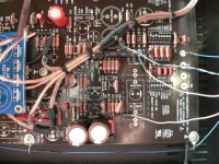
Hypnotize Remote Sense
Photo for Remote Sense, attention don't connect resistors 10R & 100R:
Negative rail:
Positive rail:
If not clear let me know, I will do more photos
Photo for Remote Sense, attention don't connect resistors 10R & 100R:
An externally hosted image should be here but it was not working when we last tested it.
Negative rail:
An externally hosted image should be here but it was not working when we last tested it.
Positive rail:
An externally hosted image should be here but it was not working when we last tested it.
If not clear let me know, I will do more photos
Last edited:
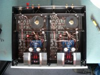
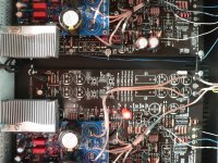
Okay, I finally finished my ONO on Hypnotize blue. I did have some oscillation problems, as you can see in post 402. there were a few foilcaps left on the ONO boards (3x47nF! ). The oscillation vanished after I removed them.
I made some wiring changes and replaced the powerR's on the Hypno into Mill's and the carbon resistors into Takman REX. I also changed the sense wiring into RG-179. The sense wiring lifted up the stereo-image and definition, more details. 🙂 Salsa with Salas !
Dragan did a marvelous job on the ONO concept and the boards are Xcellent!
I just had to try to improve the ONO.
What to do ?( made it myself for my MC cartridge but MM users can also benefit)
- make the external supply as mentioned.
- if you go single ended don't install the balanced stage
- don't install the onboard powersupply, jumper R44 so the delay stage still gets power
- remove all elco's and filmcaps in the powerlines
- make & connect the Hypnotize as mentioned, see pictures for details
- be sure to get rid of all the onboard pot's (R4/r25) measure the pot's resistance after adjusting and change it into fixed R's
- By doing this I was able to use one coupling fimcap(no C7 needed), between MC & MM stage. DC out was +/- 20mV
one coupling cap (C10)? yes, change the MC stage into the one in the drawing, you
can leave one 2sk170 on the ONO, use a resistor in serie with the 30V voltage to get the desired 9V.
From the output 1 filmcap goes directly to the MM stage,
bypass the MM switch stage. So no buffer, no cascode but it sounds better this way.
NO C19 and C37, you can put a BG or a filmcap there, but you don't want 3 caps in
the MCsignalway and 2 BG caps in serie already kill the music. just my 2 cents. 🙂
The results of this mod: clean, detailed ,powerful music with great sing along potential.
Attachments
Last edited:
Quite some work and experimentation there... Congrats. Could you find any subjective difference when gone RG-179 for sense, over previous non-shielded?
Hi Salas, my previous sense wiring was also with shielded wiring. It was coax that came from a laptop adapter. Thought it might be better to use your recommended coax and it wasn't so thick. I can't tell which did what to the sound, because I changed the resistors together with the RG-179 in one time. The sound was brighter and cleaner after all this.
RG-179 is a nice non bulky solution, with good shielding. Those 47nF capacitors were across the regs outputs where they met the Ono board? Especially with remote sensing the cables and pcb tracks little resistance vanishes and the small local films kill the ESR of the reg terminating capacitors which is calculated into the stability margin, more effectively. If the stability is marginal with such caps on main board without remote, its like migrating them right on the reg boards when with remote and the stability may just tip over.
Attachments

I use hypno pcb as a +-24 Vdc regulator but It can not stabilize Out dc - It goes higher and higher from 23 when turn on to 26 after 1 hour
my ccs current Is around 160 mA and I use adequate heatsinks on output FETs
I am using sk170s with Idss 5 - 6 mA
any ideas ?
my ccs current Is around 160 mA and I use adequate heatsinks on output FETs
I am using sk170s with Idss 5 - 6 mA
any ideas ?
- Status
- Not open for further replies.
- Home
- Amplifiers
- Power Supplies
- Using the HYPNOTIZE as a general shunt reg PCB