Hi Salas
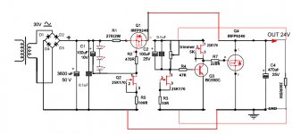
How would the schematic of the hypnotize look with sense wiring ?
The quality of the used coax cable has no influence ?
Maybe not a good idea because I have to cut coppertraces.
Erik.
How would the schematic of the hypnotize look with sense wiring ?
The quality of the used coax cable has no influence ?
Maybe not a good idea because I have to cut coppertraces.
Erik.
Its a bit weird to mod that, not very straightforward with its layout. Basically the error amp part hangs and references with a coax at the contact points with the load. Can you extrapolate from its next of kin?
shunt PS PCB - trace widths
Hey Salas and hey all,
I haven't been here in a while... As I am catching up with the discussions, I have a question for you guys. You might remember me designing some PCBs for this, which are now in final stage of prototyping.
Regarding this - and I guess the question is mainly for Salas -, I've kept the traces widths at 1.5mm on all main current draw traces (allowing, according to some online calculators for 3.2A through, plenty for most purposes), while the current sense parts of the circuit use 1mm traces (2.4A).
Everything good with my thinking? Any thoughts on particular traces (connections) that would have unseemingly high current through? For instance, any danger in the two different trace widths to throw off the current/remote sensing device?
Thank you very much for your input.
Best,
Radu.
I don't believe it is current rating that determines trace width.I've kept the traces widths at 1.5mm on all main current draw traces (allowing, according to some online calculators for 3.2A through, plenty for most purposes), while the current sense parts of the circuit use 1mm traces (2.4A).
I think trace resistance and trace voltage drop are far more important in determining trace width.
We are looking at uV values in measuring voltages and sending error signals around this PCB. I Think you should consider uV not Amperes
look at post383.The RS lines sense voltage and are high impedance. Their gauge has no consequence.
The sense circuit is isolated in the middle of that schematic.
As drawn, one can see the resemblance to a Wheatstone Bridge.
The Wheatsone bridge relies on very accurate balance of uohms to give the error signal at it's output.
I believe that layout is crucial to this balancing of uohms. Trace width may be inconsequential, but traces, their routes and lengths and where the currents travel is very important to getting best performance from the "high impedance" sensor.
BTW,
10mA through the sense circuit when controlling a 10V output is equivalent to a 1k0 impedance. That to me is a low impedance circuit.
In my view, when with the 1miliOhm Zo, 1000000x is relatively high so to consider equalizing gauges. Layout is another thing than gauge, as you said. Its primarily named a Kelvin or Thomson bridge what we do here I believe BTW.
Sorry for this question, perhaps this has been answered but i didn't find anything.
I have a Hypnotize board. What is the advantage of salvaging a hypo board over using a salas-low-voltage-shunt-reg?
Thanks for sharing some light on this...
http://www.diyaudio.com/forums/powe...w-voltage-shunt-regulator-48.html#post2103465
I have a Hypnotize board. What is the advantage of salvaging a hypo board over using a salas-low-voltage-shunt-reg?
Thanks for sharing some light on this...
http://www.diyaudio.com/forums/powe...w-voltage-shunt-regulator-48.html#post2103465
The hypno board IS a Salas low voltage shunt reg!
It has a B1 buffer and a delay circuit too, which can be left unused, or you can cut it off with a saw.
It is convenient, as it is a circuit board you can buy!
It has a B1 buffer and a delay circuit too, which can be left unused, or you can cut it off with a saw.
It is convenient, as it is a circuit board you can buy!
I know that both come from Salas and yes, it is convenient to buy a circuit board. But what about the circuit itself? Is one "better" then the other? How is the comparison between these two shunt regs?
Greetings
Greetings
There are ver 1.0 and ver 1.2 and ver Hypnotise/Mexmerize.
They are all different.
In addition there are topologies specifically designed for low output voltage, high output voltage and variable output voltage.
They are all different.
In addition there are topologies specifically designed for low output voltage, high output voltage and variable output voltage.
Tell us the reg you need and I'm sure you will be told whether the hypno is good for your purposes, adaptable, or unsuitable.
Lucas
Lucas
pcbs
(to esl 63 and others)
will keep everybody posted on the progress of the PCBs. FYI - they are for naked salas shunt reg. and are being sent to production right now.
best,
aR.
(to esl 63 and others)
will keep everybody posted on the progress of the PCBs. FYI - they are for naked salas shunt reg. and are being sent to production right now.
best,
aR.
Tell us the reg you need and I'm sure you will be told whether the hypno is good for your purposes, adaptable, or unsuitable.
Lucas
15-28V adjustable, 3A or 6A (Field Coil Driver)
+/- 5V, 30mA (small phono)
Thanks, difool
the 3A/6A option can be switchable or pluggable.15-28V adjustable, 3A or 6A (Field Coil Driver)
The 15V to 28V adjustable is easy. The variable dissipation that it introduces becomes a problem at high currents, particularly the 6A option.
You need to look at worst case operating conditions to determine what range of powers the two main transistors must be able to dissipate. I fear quite large heatsinks.
If the load were constant then shunt can be made small and cheap and perform very well. Non constant load results in a much more demanding specification.
If im using the hypno as intended (as a dcb1 buffer) and adding a few things to the load that need the same voltage (balanced to unbalanced opamp, and active volume control) Do i just adjust the current resistors?
Also need a 5.5v supply for the analog section of a dac chip (has a 5v regulator on board). Should i tape the relay supply with a lm317 style to knock the voltage down to 5.5v, or can i unequally yoke the rails of the b1 buffer and tap one rail with a lm317 for even quieter opperation?
I need to feed this guy.
Linear Regulators - Single Channel LDO - REG102-5 - TI.com
- Status
- Not open for further replies.
- Home
- Amplifiers
- Power Supplies
- Using the HYPNOTIZE as a general shunt reg PCB