I have installed the discret buffer with 2SK246 / 2SJ103 and am satisfied with the sound now. I don't feel the need to make any more modification. The sound is powerful and musical. bass is clear and not boomy. It's difficult to say whethere there was any loss in resolution; I don't here anything missing after installing the buffer.
If anyone would buy this buffer from ebay, replacing all resistors is a MUST. The description on ebay was not correct about the quality resistors being used.
If anyone would buy this buffer from ebay, replacing all resistors is a MUST. The description on ebay was not correct about the quality resistors being used.
OPA627's
Thanks for the tips. It may require a parts order and I will have to scrounge in my parts bins. Printed out the datasheet for a quick read over. I do run my buffers on + and - 15 VDC. 🙂If you do the OPA627, give it 2 x gain and 50ohm output series resistor even though it's suppose to be unity gain stable. I run it off - +15vdc rails.
Cheers George
Pedja Rogic DDNF for PCM1704
I am testing the DDNF board. Thermal bond appears to be a lot better. Cold start offset was -0.7 mV's left channel and 0.7 mV's right. After 1 hour no signal I had 1.7 mV's left and 2 mV's right. Kind of suggest DC coupling isn't all the likely. I have a CD playing now and it is connected to my Shiit Audio Magne Uber head amp. Will remeasure offset after the CD stops. I did listen to the dac with the ADEL2020 I/V on the head amp before converting to the DDNF. It sounded very much like my cousin's system in tone quality. Quite good. A brief listen with the DDNF with film and foil capacitors installed does sound a bit better with greater detail and dynamics. This is DDNF + BUF03. The sound is that of very good analog. 😉 Will report offset after CD ends as that provides some dynamic measurements. Offset measurements in all cases is before the capacitor.
I am testing the DDNF board. Thermal bond appears to be a lot better. Cold start offset was -0.7 mV's left channel and 0.7 mV's right. After 1 hour no signal I had 1.7 mV's left and 2 mV's right. Kind of suggest DC coupling isn't all the likely. I have a CD playing now and it is connected to my Shiit Audio Magne Uber head amp. Will remeasure offset after the CD stops. I did listen to the dac with the ADEL2020 I/V on the head amp before converting to the DDNF. It sounded very much like my cousin's system in tone quality. Quite good. A brief listen with the DDNF with film and foil capacitors installed does sound a bit better with greater detail and dynamics. This is DDNF + BUF03. The sound is that of very good analog. 😉 Will report offset after CD ends as that provides some dynamic measurements. Offset measurements in all cases is before the capacitor.
Pedja Rogic DDNF for PCM1704
The DC offset after playing for in excess of 90 minutes. Left channel 2.4 mV's. Right channel 2.4 mV's. This is no signal just as CD stopped. This is likely not a bad result. More than one can correct at an op amps null circuit. A DC servo might be in order. I need to do some study however I understand there are 2 types. Negative and positive. If that is the case this might be correctable. For reference I use Roger Waters "Amused to Death" CD for listening tests. Excellent for it's low level sounds on head phones and it throws a 180 degree sound field on good loud speakers. Lots of interesting low level material for testing resolution. My head amp is the Magne 2 Uber with Audio Technica ATH-M50 pro monitor headphones. Magnepan MG 2.5R Ribbon planars on the main rig with 300 Watts of class D power. 😉
The DC offset after playing for in excess of 90 minutes. Left channel 2.4 mV's. Right channel 2.4 mV's. This is no signal just as CD stopped. This is likely not a bad result. More than one can correct at an op amps null circuit. A DC servo might be in order. I need to do some study however I understand there are 2 types. Negative and positive. If that is the case this might be correctable. For reference I use Roger Waters "Amused to Death" CD for listening tests. Excellent for it's low level sounds on head phones and it throws a 180 degree sound field on good loud speakers. Lots of interesting low level material for testing resolution. My head amp is the Magne 2 Uber with Audio Technica ATH-M50 pro monitor headphones. Magnepan MG 2.5R Ribbon planars on the main rig with 300 Watts of class D power. 😉
The DC offset after playing for in excess of 90 minutes. Left channel 2.4 mV's. Right channel 2.4 mV's. This is no signal just as CD stopped. This is likely not a bad result. More than one can correct at an op amps null circuit. A DC servo might be in order. I need to do some study however I understand there are 2 types. Negative and positive. If that is the case this might be correctable. For reference I use Roger Waters "Amused to Death" CD for listening tests. Excellent for it's low level sounds on head phones and it throws a 180 degree sound field on good loud speakers. Lots of interesting low level material for testing resolution. My head amp is the Magne 2 Uber with Audio Technica ATH-M50 pro monitor headphones. Magnepan MG 2.5R Ribbon planars on the main rig with 300 Watts of class D power. 😉
Thanks for sharing your result. I think 2.4mv is trivial. On my current I/V (OPA861), I have a pot to trim the DC offset on B foot. It does however show some thermal drifts (1~3mv). I am also thinking about replacing the pot with DC servo for long term usage.
Pedja Rogic DDNF for PCM1704
Hi canvas, I appreciate you input. After 3 hours playing music I now get -1.0 mV's in the left and 0.1 mV's in the right. Long term stability is OK I think if slightly variable. As my preamp is DC coupled I'd have concerns about going straight in this way. I realize not many years ago this would have been considered a very good outcome. My first test before the special conductive epoxy was not very good. That is why I did some research. One question I have is will this thing eventually improve it's behavior? Like burning in or putting some hours on it might help? The special epoxy actually cures in 24 hours at 20 C. So I think it is cured at this point. If it changes much in the next few days I will report that. 🙂Thanks for sharing your result. I think 2.4mv is trivial. On my current I/V (OPA861), I have a pot to trim the DC offset on B foot. It does however show some thermal drifts (1~3mv). I am also thinking about replacing the pot with DC servo for long term usage.
Arcam alpha 5+ / TDA1541A
HI
this thread has me interested enough to stick my neck out from the occasional lurking.
Background/motivation:
As my prime tube based system (TD125/Benz wood + OPera Ref 2.2 Mkiii -> MG 1.6QR) is in different stages of parking and modding -> pulled my secondary SS based system out (TD124/Shelter 501 + Arcam a5+ -> Avance Dana 2-way)
Initially not all operational either, the Acram down from the loft , recapping, new/old laser. Coupling cap changed for MKP (can't hear difference between a Auricap and the Clarity ESA I have in now). Then rolling opamps (original op27 + ne5344, new opa1611, lt1028, ad825, lt1357, lt1361). IV I can hear a strong impact - on the filter not so much. AT moment settled on LT1028ACN IV and LT1357 on filter = combo gives me the most air and musical presence without to much 'whining' and 'shrill' in the middle and top ..but still a bit on the bright side for my taste (I don't care about neutral or audiophile/highend-ism .. I like colored sound so I can feel the smoke in the bar, ask for another pint and the feet keep stomping along)
Questions wrt AD844 IV:
1) how would you describe the impact of the AD844 IV compared to a normal OPamp IV ..say on a color scale : warm/layed back (OPAish) - clear (LTis) - 'grunt' & bright (ADish) .. and on a detail scale : all hidden - airy & resolving but musical - x-raying all
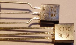
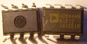
2) I already bought 2 different set of 2sk170 (gr and bl version) from small electronics dealers in Denmark. 6 psc AD844 from Reichelt in Germany.. but see several places there is discussion about such items being genuine:
so Fine or Fake ? (see attached Photos)..the gr set has curved legs?.
Anyway did make a Broberly jig to measure Idss and Vp and got
gr : Idss 3.1 to 3.3 mA, Vp -0.309 to -0.312V
bl : Idss 11.8 to 12.8 mA, Vp -0.998 to -1.044V
this seems high values for Vp? (and over spec for Idss on bl) .. though gives gmo of 20 (gr) to 22-26 (bl) which seems in accordance w specs.
(well this has been nagging me, so I ordered a small peak atlas dac75 curve tracer to test further)
which version (gr or bl) to use for bias circuit?
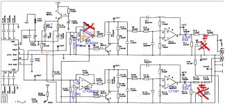
3) using original Rogic IV schematic (as in his AYA DAC) is a minimum PCB/footprint change to the Arcam Alpha 5+ DAC board possible (see attached schematic) - and reversible so I reasonably can jump back forwards for A-B compare.
On schematic L ch indicated how AD844 IV could be put in - on R ch how I have it now.
I.e. I could 'glue' a 3stack AD844 'package' together as a drop-in on the Opamp socket - only cutting the feedback resistor open
The IV load at pin 5 I can put directly on the opamp to pin 3. The pin 6 outputs merged via 100R could do on the stacking .. but then question of mechanically to get the end of resistor into socket at pin 6 (if it will work .. will test )
BUT can I reuse the biasing circuit already there? this is the biggest question - or must I make a new one as Rogics jfet based? (and if I do, would I be able to operate the normal opamp IV w this new bias arrangement?)
thanks
/Patrick
HI
this thread has me interested enough to stick my neck out from the occasional lurking.
Background/motivation:
As my prime tube based system (TD125/Benz wood + OPera Ref 2.2 Mkiii -> MG 1.6QR) is in different stages of parking and modding -> pulled my secondary SS based system out (TD124/Shelter 501 + Arcam a5+ -> Avance Dana 2-way)
Initially not all operational either, the Acram down from the loft , recapping, new/old laser. Coupling cap changed for MKP (can't hear difference between a Auricap and the Clarity ESA I have in now). Then rolling opamps (original op27 + ne5344, new opa1611, lt1028, ad825, lt1357, lt1361). IV I can hear a strong impact - on the filter not so much. AT moment settled on LT1028ACN IV and LT1357 on filter = combo gives me the most air and musical presence without to much 'whining' and 'shrill' in the middle and top ..but still a bit on the bright side for my taste (I don't care about neutral or audiophile/highend-ism .. I like colored sound so I can feel the smoke in the bar, ask for another pint and the feet keep stomping along)
Questions wrt AD844 IV:
1) how would you describe the impact of the AD844 IV compared to a normal OPamp IV ..say on a color scale : warm/layed back (OPAish) - clear (LTis) - 'grunt' & bright (ADish) .. and on a detail scale : all hidden - airy & resolving but musical - x-raying all
2) I already bought 2 different set of 2sk170 (gr and bl version) from small electronics dealers in Denmark. 6 psc AD844 from Reichelt in Germany.. but see several places there is discussion about such items being genuine:
so Fine or Fake ? (see attached Photos)..the gr set has curved legs?.
Anyway did make a Broberly jig to measure Idss and Vp and got
gr : Idss 3.1 to 3.3 mA, Vp -0.309 to -0.312V
bl : Idss 11.8 to 12.8 mA, Vp -0.998 to -1.044V
this seems high values for Vp? (and over spec for Idss on bl) .. though gives gmo of 20 (gr) to 22-26 (bl) which seems in accordance w specs.
(well this has been nagging me, so I ordered a small peak atlas dac75 curve tracer to test further)
which version (gr or bl) to use for bias circuit?
3) using original Rogic IV schematic (as in his AYA DAC) is a minimum PCB/footprint change to the Arcam Alpha 5+ DAC board possible (see attached schematic) - and reversible so I reasonably can jump back forwards for A-B compare.
On schematic L ch indicated how AD844 IV could be put in - on R ch how I have it now.
I.e. I could 'glue' a 3stack AD844 'package' together as a drop-in on the Opamp socket - only cutting the feedback resistor open
The IV load at pin 5 I can put directly on the opamp to pin 3. The pin 6 outputs merged via 100R could do on the stacking .. but then question of mechanically to get the end of resistor into socket at pin 6 (if it will work .. will test )
BUT can I reuse the biasing circuit already there? this is the biggest question - or must I make a new one as Rogics jfet based? (and if I do, would I be able to operate the normal opamp IV w this new bias arrangement?)
thanks
/Patrick
Attachments
AD844 Stacking...
Hi Patrick, Well first off the best standard feedback I/V I ever tried is the ADEL2020. One thing I never tried was the 2SK170 current source with that chip and now I consider that mandatory. At least with a TDA1541 or (A) chip. The AD844 stacked (3X) using 100 Ohm series output resistors is less satisfying then the previously mentioned ADEL2020. Very good detail and resolving power however the bass is anemic in most systems. It is a different story when applied as a current mirror taking pin 5 as an output to a high impedance buffer. I recommend the BUF03 for that. I am told a OPA627 is awesome as a buffer. I have some parts on order to try that this weekend. An alternative to the 2SK170 is the BF245A. Has different pin outs so beware. I believe the BF245A is more stable in operation as a current source. Filter... I left active filters some time ago. If your interested I will show a simple alternative that removes the active devices from the signal path. Pictures... The 2SK170's you show look real. If the face has been sanded it is a fake. Should be fine gold lettering. I'd use the GR version for a 2 mA current source. It might be more stable that way. AD844's are typically made in the Phillipines as shown so are likely real. Only way to be sure is if the pin 5 connection works. A fake won't. I hope I addressed most of your questions. I am currently working with Pedja's DDNF boards both with TDA1541's and PCM1704's. 😉HI
this thread has me interested enough to stick my neck out from the occasional lurking.
Background/motivation:
As my prime tube based system (TD125/Benz wood + OPera Ref 2.2 Mkiii -> MG 1.6QR) is in different stages of parking and modding -> pulled my secondary SS based system out (TD124/Shelter 501 + Arcam a5+ -> Avance Dana 2-way)
Initially not all operational either, the Acram down from the loft , recapping, new/old laser. Coupling cap changed for MKP (can't hear difference between a Auricap and the Clarity ESA I have in now). Then rolling opamps (original op27 + ne5344, new opa1611, lt1028, ad825, lt1357, lt1361). IV I can hear a strong impact - on the filter not so much. AT moment settled on LT1028ACN IV and LT1357 on filter = combo gives me the most air and musical presence without to much 'whining' and 'shrill' in the middle and top ..but still a bit on the bright side for my taste (I don't care about neutral or audiophile/highend-ism .. I like colored sound so I can feel the smoke in the bar, ask for another pint and the feet keep stomping along)
Questions wrt AD844 IV:
1) how would you describe the impact of the AD844 IV compared to a normal OPamp IV ..say on a color scale : warm/layed back (OPAish) - clear (LTis) - 'grunt' & bright (ADish) .. and on a detail scale : all hidden - airy & resolving but musical - x-raying all
2) I already bought 2 different set of 2sk170 (gr and bl version) from small electronics dealers in Denmark. 6 psc AD844 from Reichelt in Germany.. but see several places there is discussion about such items being genuine:
so Fine or Fake ? (see attached Photos)..the gr set has curved legs?.
Anyway did make a Broberly jig to measure Idss and Vp and got
gr : Idss 3.1 to 3.3 mA, Vp -0.309 to -0.312V
bl : Idss 11.8 to 12.8 mA, Vp -0.998 to -1.044V
this seems high values for Vp? (and over spec for Idss on bl) .. though gives gmo of 20 (gr) to 22-26 (bl) which seems in accordance w specs.
(well this has been nagging me, so I ordered a small peak atlas dac75 curve tracer to test further)
which version (gr or bl) to use for bias circuit?
3) using original Rogic IV schematic (as in his AYA DAC) is a minimum PCB/footprint change to the Arcam Alpha 5+ DAC board possible (see attached schematic) - and reversible so I reasonably can jump back forwards for A-B compare.
On schematic L ch indicated how AD844 IV could be put in - on R ch how I have it now.
I.e. I could 'glue' a 3stack AD844 'package' together as a drop-in on the Opamp socket - only cutting the feedback resistor open
The IV load at pin 5 I can put directly on the opamp to pin 3. The pin 6 outputs merged via 100R could do on the stacking .. but then question of mechanically to get the end of resistor into socket at pin 6 (if it will work .. will test )
BUT can I reuse the biasing circuit already there? this is the biggest question - or must I make a new one as Rogics jfet based? (and if I do, would I be able to operate the normal opamp IV w this new bias arrangement?)
thanks
/Patrick
Very hard to get a fake AD844, as no other opamp I know of has a pin 5 TZ output to fake it with. If the pin 5 TZ output works it's real in my opinion.
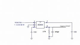
The best sound I got with a PCM1704K dac was a 3 stack 844 using pin 5 to the opa627 with 2 x gain for the output buffer.
Cheers George
The best sound I got with a PCM1704K dac was a 3 stack 844 using pin 5 to the opa627 with 2 x gain for the output buffer.
Cheers George
Hi George
May I ask what regulators are you using for the Buf 03 ?
I build a zener/emitter series reg but have issues with it
Thks
May I ask what regulators are you using for the Buf 03 ?
I build a zener/emitter series reg but have issues with it
Thks
I.e. I could 'glue' a 3stack AD844 'package' together as a drop-in on the Opamp socket - only cutting the feedback resistor open
The IV load at pin 5 I can put directly on the opamp to pin 3. The pin 6 outputs merged via 100R could do on the stacking .. but then question of mechanically to get the end of resistor into socket at pin 6 (if it will work .. will test )
Try not to mess up with original circuit. I'd suggest building up the circuit on a breadboard, so that you can switch back more easily. This is how I did it on my DAC.
This I/V is fun to play with. It's got a lot of potential. I'm sure it will sound better than original circuit.
BUF03's
George has switched to OPA627's. I am using LT1083 based regulators configured as + and -. BUF03's run quite a lot of current. Runs in Class A so you really need to use a good regulator with low output impedance. I use Silver plated Teflon insulated wire to the board. Maybe a bit overkill however I have had no issues. Bypasses on my BUF03 board are 220 uF Nichicon bypassed with 0.1 uF Wima's. Hope you have a good heatsink or set the rails to less then + and - 15 VDC. They really cook. I have not had any failures so far. 😀Hi George
May I ask what regulators are you using for the Buf 03 ?
I build a zener/emitter series reg but have issues with it
Thks
Yes do this!
Totally agree... A fresh effort is better then messing about and it allows you to go back for reference.Try not to mess up with original circuit. I'd suggest building up the circuit on a breadboard, so that you can switch back more easily. This is how I did it on my DAC.
This I/V is fun to play with. It's got a lot of potential. I'm sure it will sound better than original circuit.
Hi George
May I ask what regulators are you using for the Buf 03 ?
I build a zener/emitter series reg but have issues with it
Thks
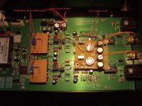
This is a pic of my early mods you can see the adjustable +-regs at the top PCM1704's are under the DC offset nulling vero boards
I just used the 1amp 15vdc +- TI regulators that were in the Cary I don't use the DC offset nulling anymore, no need for it, and now it's 3 stack 844's and changed the BUF03 for OPA627's now. That was the best I could get. Everything DC coupled from dac output to the output RCA's just 1mv +- offset.
Cheers George
Attachments
Last edited:
This is a pic of my early mods you can see the adjustable +-regs at the top PCM1704's are under the DC offset nulling vero boards
I just used the 1amp 15vdc +- TI regulators that were in the Cary I don't use the DC offset nulling anymore, no need for it, and now it's 3 stack 844's and changed the BUF03 for OPA627's now. That was the best I could get. Everything DC coupled from dac output to the output RCA's just 1mv +- offset.
Cheers George
Hi George,
I have been following your journey both here and on SNA and have been collecting buf03's, ad844's, powersupply's etc with the anticipation of using them after a AD1865 I out and with a tda1541 audial when built.
Can you clarify your schematic as it has changed from your initial findings with offset etc. I just want to be sure of what I am building so as no to fry anything.
I have fried a linemagnetic dac and one other ad1856 in the last few months.
Apologies if this seems trivial however I need to visualise the schematic and seem to be over cautious after the last mistakes.
I really appreciate your help and time.
Cheers
Greg
Ps missing your posts on SNA 🙂
Thanks Torchwood421 & George
well I consider taking this a step at a time, keeping changes to the PCB minimal for reversibility so far as it can go.
Now what comes after the IV I can wait with till later (and by the way I still have SAA7220 dig filter in there, BUT the Arcam Alpha5+ is not so stupidly build. It does not take the dirty clock out of SAA7220 and route it in to the DAC - instead a common clock split and individually buffered so TDA1541 gets a clean clock = one of LCaudio first clock designs)
BUT before the IV .. for simplest test just to get going
- could I use the bias circuit already existing as is (around the BC547)? -> else forced to use Rogics JFET biasing for starters = but reversibility for other opamps when swapping back to normal opamp IV?.
- do I need to put in 1.8nF from bias to ground for starters
- and can I leave the shunt network at the input (originally 1K but I further shunted it w 1uF + 2.2Ohm following suggestion by Rutgers wrt LT1028 IV)
/Patrick
Last edited:
Try not to mess up with original circuit. I'd suggest building up the circuit on a breadboard, so that you can switch back more easily. This is how I did it on my DAC.
This I/V is fun to play with. It's got a lot of potential. I'm sure it will sound better than original circuit.
Hi Canvas
ok I get your point.. and should I do a lot of changes I agree to keep it on a separate 'platform'. But for starters I think I can make a AD844 package w the TZ network so it is just a drop in on the opamp socket. The feed back resistor I need to cut open anyhow.
But the bias in the front that is where the changes might come. If able to use existing bias no changes needed. But if I need to do the Rogic JFET thing.. well maybe I have to put it on small bread board as you have done and just cut the old bias netw open
thanks
/Patrick
Hi George,
I have been following your journey both here and on SNA and have been collecting buf03's, ad844's, powersupply's etc with the anticipation of using them after a AD1865 I out and with a tda1541 audial when built.
Can you clarify your schematic as it has changed from your initial findings with offset etc. I just want to be sure of what I am building so as no to fry anything.
I have fried a linemagnetic dac and one other ad1856 in the last few months.
Apologies if this seems trivial however I need to visualise the schematic and seem to be over cautious after the last mistakes.
I really appreciate your help and time.
Cheers
Greg
Ps missing your posts on SNA 🙂
3 stack 844's with nulling offset pins 1 and 8 only used on one of the 844's.
Cheers George
Attachments
- Home
- Source & Line
- Digital Line Level
- Using the AD844 as an I/V