Triple stack question and volume control
Hi Guys
one question to stacking.
i´m using ad844 ala pedja in my marantz cd80 (only double stacked and one output buffer using)
did you compare all 3 buffers in parallel instead of one?
to the volume control. my main setup is a 1792 dac wit passive iv with 3 ohm mills. then i use my vcuumstate rtp3 phono stage with the eq switched of as a gain stage. works fine and sounds good.
then i took my sowther 8347 (that had no chanche in my tda1541 against the ad844 implementation..) and inserted it between the mills and the phono stage.output after 8347 is 230mv eff with 0dbfs
phono stage rises this to 30Veff and i had to reduce line stage gain-(easy-have a switch for gain setting)
but the sound-so much more microdetails and dynamik-so maybe its better first to amplify anything and then reduce at a very late stage in the system?
had anyone similar experience-i know system is then very tailor made and difficult to swap different amps etc.
thanks
klaus
Thanks George, my bad. It's the SA-11S1
The SM11 is the matching power amp, which I also have.
It must have been the previous model Marantz that used the Cirrus chip.
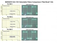
Arty, I found something I had stored on my puter, thought you'd be interested in.
The filter 2 looks the best but it's 5db down at 20k.
Cheers George
Attachments

Hi,
the SK170 or SK369 are not the best choice as current source JFETs, at least not used alone.
They are optimized for low voltage noise figures, which aren´t of that much interest when used as CCS.
Their Gate structure is therefore of large geometry, resulting in increased capacitance figures.
Also their Idss is rather low, meaning that the source degeneration resistors will be rather small in value too, resulting in rather mediocre dynamic impedance.
Matters can be improved by cascoding with a second JFET.
For this special application and voltage and current levels the xx4392 or xx4391 would suffice as cascoding JFETs, as their high Idss and Vgs allow for sufficient Drain-Source voltage over the cascoded device.
To achieve best rejection figures the Vdg should be >2x Vgs(off).
The cascode configuration improves jejection, increases impedance --> current becomes more constant, and keeps the capacitance low.
Alternatively to the cascode teh xx4392 or xx4391 used as single device will be better than the SK170/369.
Their much higher Idss requires source resistors with higher values to degenerate to the required current value.
The impedance and rejection ratio improve, capacitance is lower and very probabely even noise figures may improve (a case where higher resistance can improve noise figures)
In any case, will the cascode or the alternative JFETs be closer to the ideal CCS than the SK170/369 ... and cheaper and easier to source anyway.
jauu
Calvin
Current Source
Hi kp93300, Sorry for the late reply here. You have 2 options on VR1. If you use the BF245A JFET VR1 is 500 Ohms. If you use a 2SK170 JFET use a 200 Ohm trimmer for VR1. I used the 2SK170 version. My understanding is the 2SK170 is more stable over time. I found no issues with using a 2SK170 for a current source. So can't speak to Calvin's comment. The source of this circuit is Pedja Rojic's Aya DAC. At one time he had his schematics posted at his website under DIY. That was some time ago. If you would like me to email you that AYA DAC schematic just send me a PM with an email address and I can send that to you. Adjustment: Here is how you adjust it. You want to place your DMM looking at the input pin of the AD844 (same as the output pin of the 1541A) and ground. The idea is to adjust the input (to the 844) so it is resting at 0 mV's (no signal). The current source is to eliminate the DC offset from the 1541A. Install the nulling circuit at the 844 for output nulling. Hope that helps. 🙂I am using the schematic from the first post for TDA 1541 A.
I am building it on a breadboard
Can someone give me an approximate value of the VR1??
How do you trim VR1 ?
thanks
kp93300
VR1
In hind sight, stick with 500 Ohm trimmer. Depending on the grade of 2SK170, you may need a bit more range. I think I used 2SK170GR's. Beware of fakes out there. Genuine Toshiba is tough to find. 😉
I am using the schematic from the first post for TDA 1541 A.
I am building it on a breadboard
Can someone give me an approximate value of the VR1??
How do you trim VR1 ?
thanks
kp93300
In hind sight, stick with 500 Ohm trimmer. Depending on the grade of 2SK170, you may need a bit more range. I think I used 2SK170GR's. Beware of fakes out there. Genuine Toshiba is tough to find. 😉
Georgehifi: Saw the PS load question on the "other place", digital vs analog loading. Can't answer you question but as you already know the Data sheet claims no gain in separate supplies and should be keep within +- 0.1vdc all voltages. I suspect that conclusion.
I have gone from three pin regulators(stock), to emitter follower, and now "super regulator" type supplies for the +- 5vdc dac supplies and +-15vdc stacked AD844s. Each dac chip power supply pin has a separate supply path but same source. Each step up in PS is a nice improvement.
I have also change thru a few TZ resistors, Standard MF, to RC60 mils and now a VTA foil. Again all a step up for me.
Right now the unit is in for some "clean up" as a result of all the changes. Thru pin components changed and rechanged leave there mark. Still having fun here!
Last edited:
470 pF Filter Cap
Hi George, Well I finally felt up to some DIY today. I installed the 470 pF Polypropylene 100V 2.5% Wima's and some 1 Meg load resistors at the RCA's. My TZ resistors are 2.5KOhm. Sounds super dynamic. Not sure if there is enough filter for my system.... I'll give her some time. First impression is pretty good. The Edcor's slightly dulled the transient response although it was silky smooth before the change. 8 Times OS gives 352.8 Khz image (CD), wonder how much stop band that will ultimately have. Happy Holidays's
Yep that's it, a 2.7kohm TZ resistor with 470pf across it which gives -3db at 125khz.
With this I only have a couple of mV of hf noise on the output of the 844's buffer at max digital volume. When cd's are in between tracks or no music playing you swear the system is switched off.
Cheers George
Hi George, Well I finally felt up to some DIY today. I installed the 470 pF Polypropylene 100V 2.5% Wima's and some 1 Meg load resistors at the RCA's. My TZ resistors are 2.5KOhm. Sounds super dynamic. Not sure if there is enough filter for my system.... I'll give her some time. First impression is pretty good. The Edcor's slightly dulled the transient response although it was silky smooth before the change. 8 Times OS gives 352.8 Khz image (CD), wonder how much stop band that will ultimately have. Happy Holidays's
The cap across the TZ resistor, filters any HF noises coming from the dac chip.
Cheers George
Cheers George
DTS Master
Watching a Blu ray with DTS-Master and it is super clean. It could be I am hearing more detail. Time will tell. When my parallel DAC had "to little filtering" I heard a sheen over the music. I actually don't hear anything like that here. Plan is to burn her in for a while before any critical listening or comparisons. It out classes my CS4398 DAC without much effort. 😉 I do understand about the difference between DAC noises and oversampling products. Dave
The cap across the TZ resistor, filters any HF noises coming from the dac chip.
Cheers George
Watching a Blu ray with DTS-Master and it is super clean. It could be I am hearing more detail. Time will tell. When my parallel DAC had "to little filtering" I heard a sheen over the music. I actually don't hear anything like that here. Plan is to burn her in for a while before any critical listening or comparisons. It out classes my CS4398 DAC without much effort. 😉 I do understand about the difference between DAC noises and oversampling products. Dave
I found with PCM1704 after a bit of listening the best with this TZ resistor/cap filter calculated was to set the -3db at 125khz this gave a slight cut .5db at 20khz with minimal inconsequential noise on the output.
This TZ filtering may be different with the TDA1541 as the last time I remember one of these without any filter the noise was very high, not like the PCM1704
Cheers George
This TZ filtering may be different with the TDA1541 as the last time I remember one of these without any filter the noise was very high, not like the PCM1704
Cheers George
Arty, I found something I had stored on my puter, thought you'd be interested in.
The filter 2 looks the best but it's 5db down at 20k.
Cheers George
George,
Filter number 2 appears to be a 'short' impulse response linear phase filter featuring minimal pre and post ringing, a relatively slow in-band roll off and consequently poor ultrasonic image rejection. Filter number 3 appears to be a typical 'long' impulse response linear phase filter featuring significant pre and post ringing, a relatively flat in-band amplitude response and good ultrasonic image rejection.
Filter number 1 is the most unusual. It appears to be a combination linear phase-minimum phase filter. The linear phase portion appears to have a 'short' impulse response, while the minimum phase portion appears to have a 'long' impulse response. Thise combination can produce a flat in-band amplitude reponse with good ultrasonic image rejection, minimal pre-ringing and a reduced post ringing.
Last edited:
George,
Filter number 2 appears to be a 'short' impulse response linear phase filter featuring minimal pre and post ringing, a relatively slow in-band roll off and consequently poor ultrasonic image rejection. Filter number 3 appears to be a typical 'long' impulse response linear phase filter featuring significant pre and post ringing, a relatively flat in-band amplitude response and good ultrasonic image rejection.
Filter number 1 is the most unusual. It appears to be a combination linear phase-minimum phase filter. The linear phase portion appears to have a 'short' impulse response, while the minimum phase portion appears to have a 'long' impulse response. Thise combination can produce a flat in-band amplitude reponse with good ultrasonic image rejection, minimal pre-ringing and a reduced post ringing.
Yeah those from Marantz just look like different order filters, 1st 2nd 3rd 4th and so on. Always best with 1st if no **** gets through and the audio band isn't chopped into and phase shift is kept low.
That's why the PCM1704 impressed me, at only .5db down at 20khz with 1st order I was only getting a couple of mV of noise/hash at the output, I don't think this is achievable with a TDA1541.
PS: Just found my screen shots http://www.diyaudio.com/forums/digital-source/227677-using-ad844-i-v-8.html#post3338183
Cheers George
Last edited:
DAC noise filter
Hi George, Enjoying the PCM1704 DAC. Yes... The TDA1541's requires a different value as I recall in that TZ position. I was gifted with another pair of PCM1704's that are ungraded samples. Also a pair of PCM1702's. I am close to finishing this version of the 1704. I have just a few minor experiments and then looking at boxing the project. My parallel TDA1541A S1 Crown will take quite a bit more work in the critical I/V area. The 6GM8/2SK170 SRPP is quite good although I thing I can beat that with some different circuitry. 😉
I found with PCM1704 after a bit of listening the best with this TZ resistor/cap filter calculated was to set the -3db at 125khz this gave a slight cut .5db at 20khz with minimal inconsequential noise on the output.
This TZ filtering may be different with the TDA1541 as the last time I remember one of these without any filter the noise was very high, not like the PCM1704
Cheers George
Hi George, Enjoying the PCM1704 DAC. Yes... The TDA1541's requires a different value as I recall in that TZ position. I was gifted with another pair of PCM1704's that are ungraded samples. Also a pair of PCM1702's. I am close to finishing this version of the 1704. I have just a few minor experiments and then looking at boxing the project. My parallel TDA1541A S1 Crown will take quite a bit more work in the critical I/V area. The 6GM8/2SK170 SRPP is quite good although I thing I can beat that with some different circuitry. 😉
maybe the internal buffer of this chip gets a bad rap because it is weak (?high impedance).
pin 6 sounds better with an external buffer connected to it. the transparency actually seem to increase to the point where the difference is no longer night and day as it was when comparing pin 5+buffer vs pin 6 alone.
so the transparency actually increases for pin 6 with a buffer following it.
am i just imagining this or is this technically possible?
I also have stopped using the internal buffer, it was nice but lacked balls.
I've also stopped using the BUF03 external buffer also, it had the balls, and big ones too. But I found that a simple OPA627 with 1.5 x gain was even better, had almost as much balls as the BUF03 but has transparency and sweetness, and seems to be better at sound staging as well.
PS: all running from TZ pin 6
Cheers George
OPA627's
Hi George, Yes. The triple stack is nice. Sweet and analog sounding. Maybe looses that jump factor. Still a BUF03 believer... I upgraded the Pedja DDNF discrete circuit in the TDA1541 DAC. It is still king. I am looking for a board house to get more DDNF boards made. I want to use one in the PCM1704 DAC in place of the triple stack. No DC offset to worry about on that. Which OPA627? DIP or SOIC? They don't sound the same between packages. The Dies are actually different. DaveI also have stopped using the internal buffer, it was nice but lacked balls.
I've also stopped using the BUF03 external buffer also, it had the balls, and big ones too. But I found that a simple OPA627 with 1.5 x gain was even better, had almost as much balls as the BUF03 but has transparency and sweetness, and seems to be better at sound staging as well.
PS: all running from TZ pin 6
Cheers George
I used the DIP one which I've had for years in my stocks in a 8 pin cradle so I can swap and try different opamps.
Cheers George
Cheers George
OPA627's
Hi George, Same here, I have a pair from the 1990's in DIP. I also have a pair in SOIC on a DIP adapter. The older part is slightly darker sounding not bad in anyway. Just for reference what speakers do you have? We tend to hear exactly the same thing. I did find a board house yesterday and will order boards for the DDNF. I won't offer the few spares here until I build the first one and make sure there are no issues. Dave 🙂I used the DIP one which I've had for years in my stocks in a 8 pin cradle so I can swap and try different opamps.
Cheers George
- Home
- Source & Line
- Digital Line Level
- Using the AD844 as an I/V