I have modified cd player with PCM63P-KY. After many changes i have come to very precise relaxed sound. Maybe a little sterile. Then I tried 3 stacked AD844 and the result is:
- the sound is not as accurate
- all tones are slightly rounded
- middle tones is much more comfortable
- AD844 and PCM63 are warmer
I do not know if this is what pleases me but I really miss the exact sound that I had.
- the sound is not as accurate
- all tones are slightly rounded
- middle tones is much more comfortable
- AD844 and PCM63 are warmer
I do not know if this is what pleases me but I really miss the exact sound that I had.
Maybe these speakers are very revealing. I can actually hear the pianist´s activity on the pedals of his piano and the breathing of James Galway playing his flute. I have had these for over twenty years and I have never heard them sounding so realistic. I have to add that my DAC has the master clock and the players are modified to be slaved to this master clock via fiber optic link ST connection. So the clock generated from the SPDIF data stream is not used as a master clock in the DAC.
https://picasaweb.google.com/tsundsd/October292012?authkey=Gv1sRgCPv0qfqR9oKrAw#5807456458436717122
https://picasaweb.google.com/tsundsd/October292012?authkey=Gv1sRgCPv0qfqR9oKrAw#5807456458436717122
Last edited:
I have modified cd player with PCM63P-KY. After many changes i have come to very precise relaxed sound. Maybe a little sterile. Then I tried 3 stacked AD844 and the result is:
- the sound is not as accurate
- all tones are slightly rounded
- middle tones is much more comfortable
- AD844 and PCM63 are warmer
I do not know if this is what pleases me but I really miss the exact sound that I had.
I think that maybe you are hearing what I first thought ( http://www.diyaudio.com/forums/digital-source/227677-using-ad844-i-v-56.html#post3608913 ) when going from double to tripple. I thought maybe the double had a little more leading edge than the tripple, but now after living with the tripple, it maybe just less leading edge distortion, when I try 4 stack I'll get a better idea.
Cheers George
I think the more parallel operational amplifier there is a slight delay in the signal between them and the edge of tones are losing and gets a holographic sound effect. Everyone who listened said the better. For me it sounds more like all round system, like Revox or Bang Olufsen.
I had Revox B242 first thing I did was reduce capacity between pins 5 and 8 NE5534 from 47pF to 5pF. I love it when the sound is so accurate that I hear even the slightest change in the system in terms of cables, connectors.
I had Revox B242 first thing I did was reduce capacity between pins 5 and 8 NE5534 from 47pF to 5pF. I love it when the sound is so accurate that I hear even the slightest change in the system in terms of cables, connectors.
Last edited:
Hi impuls, my thoughts exactly about paralleling devices. I too lost pin point imaging when i paralleled 844. Same thing again with tda1543 that ive noticed for a while now. I think with 844 the benefits outweigh the con. And this smudging effect is rather pleasant if you didn't know what to listen for
With the PCM1704 (+-1.2mA) dacs on my system (big esl/hybrid based) not the Wilson Halcro system that we've been doing the A/B's on. I may favour the 2 stack, one day I will go back and see what it sounds like again.
Cheers George
Cheers George
I once simulated the AD844 some years ago. It showed excellent performance, so long as the transistors were very closely matched. Relatively small transistor parameter mismatch produced relatively significant increases in THD,, which is not surprising in a complementary topology used open-loop. That's what is so nice about the AD844 IC, the integrated transistors on the monolithic chip are apparently well matched.
I feel that a discrete, high quiescent current version can perform better if pains are taken to match and thermally couple the transistors, which may prove problematic. This suggests to me the use of monolithic transistor arrays to build a diy implementation.
I feel that a discrete, high quiescent current version can perform better if pains are taken to match and thermally couple the transistors, which may prove problematic. This suggests to me the use of monolithic transistor arrays to build a diy implementation.
The AD1865 dac can only give out 1mA and skouliki found a difference with 3 stack, so this means to me that it not a current starvation thing. I think it's the lowering of input impedance that were hearing.
Cheers George
Today I have simulate the AD844, and to have the 50 ohms of input impedance the 844 specifies , the quiescent current in the input stage had to be only 300uA .
then I test the distortion with an input signal of 0.6ma at 1khz to simulate a pcm1704 at -6db full scale, the distortion was 0.12% .
With 3x AD844 in parallel the distortion goes down to 0.008%.
So, even that the AD844 has only less than 500uA of quiescent current in the input stage, the distortion is not to high, due to the complementary topology of the chip , that cancells at the output the huge quantity of pair harmonics that are created in the input.
the AD1865 also benefits from paralleling 844.
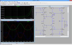
In the image is possible to see at green the current at emiter of Q4 and Q14 and at red the output current. the distortion of the input current is so huge that can be easily seen. the upper graph is the input impedance of the circuit (50 ohms).
So, yes, the 844 have a current starvation problem.
Increasing the quiescent current will also bring the input impedance down, at 10mA the input impedance is less than 2 ohms. So there is something to gain in doing a discrete circuit with a increase quiescent current.
I have seen the s3tup's discrete 844 (thanks george), but there is a lot of things that I would do different, so I will do my one version.
Attachments
Great work Sergio, how can we up the quiescent current on the 844's input. Is it what Pedja's circuit has here and is it enough. http://www.diyaudio.com/forums/digital-source/227677-using-ad844-i-v.html#post3316991
Cheers George
Cheers George
Last edited:
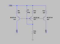
Yes George, the Pedja's circuit should work for pcm1704, but it will have a dc offset at the output , the best is to inject a current in the pin 2 and the same current in pin 5 , the circuit in the image should be better , as there is no offset voltage at the output , R14 can be a trimer, to regulate the output voltage offset . In simulation the input impedance from the AD844 falls to 6 ohms, the distortion is 0.01% mainly 2º harmonic, using this technique the AD844 loses the complementary characteristic.
The sound from this technique should please the tube lovers.
If someone wants to use this , please be carefull as I never try this with a real AD844 , and it can damage the 844 chip , so do not connect the dac chip until you have certain that everything works fine , and the 844 does not overheat. I think that every thing should work o.k. , but until we try we never know. 😉
Attachments
Serg, thanks for that explaintion, a couple more questions if you don't mind.
With Pedja's circuit which is far simpler, I can trim out any dc offset with the BUF03 buffer dc offset trimer which in the data sheet says is good for +-80mV range. Do you think it will be within trim range with Pedja's circuit insitu.
And on his circuit what do you think is the value of his trimpot is? and how would you say to set this?
Cheers george
Attachments
Stacking avert techniques
Hi Guys
I promised George to post this last time we met up on August the 1st, and of course we discussed matters related to AD844's.
I said I would show a couple of techniques that overcomes the need for stacking.
I am not saying not to stack, but simply that the reason for stacking is that in the OTA part (Diamond Transistor) current is so low, almost certainly sub 1mA. Hence, what other shots do we have in our armory? Worth at least looking at.
George feels the input impedance, what is seen by the DAC, is also important to keep low, and indeed the ideal has always be zero Z. But does 0 to 50 Ohm make that much of a difference? I see many using TDA1541A into 33R and then tubes afterward (a la Steve Garland's KillerDAC). They don't complain about the sound. How much does the DAC deteriorate not seeing zero Z? It's a matter of degree. Relative to the high Z of the DAC, it can be argued minimally.
Hera two techniques shown here will reduce the DAC's current to overwhelm that of the OTA part of AD844:
Technique 1.
Zero current induced into the OTA.
The 39R here replicates what is normally seen on "-" input in Pedja's original circuit, which I saw first time about ten years ago.
Now, with this arrangement, then all DAC's current goes to ground via 39R, as "+" input is high Z.
The component values shown are only guides and the caps are filters and may/will vary from DAC to DAC (use one or the other or both, but get their values right as they do affect the sonics). The 1K8 value is adjusted to gives 2.0V RMS output. Any DC offset can be trimmed used by the facility inbuilt in the buffer, by simply adding a 20K trimpot from Pin 1 and Pin 8 and the wiper to Pin 7.
Note, as George told me he does, the output can be taken from Pin 5 (by-pass internal buffer) and then use a separate buffer like BUF03 etc.
Technique 2.
This one may interest George as it actually makes the DAC see a much lower Z than even stacking could achieve.
The nominal input Z on "-" is 50 Ohm (that may be a max spec or more like 40?). But using a much lower value (about 1/10th) the current gets shunted to ground and very little DAC current ends up upsetting the OTA.
This may well be an equivalent of stacking up to 10 x AD844?
All the other details as far as constructing this, is the same as for Technique 1. That 18K value shown indicates that much higher gain is required, but the AD844 is suitably low noise and can handle it, so adjust 18K to give 2.0V RMS output.
The other alternative: OPA860/861:
If there was a way of increasing the current in the OTA of AD844, then stacking could also have been avoided that way. But there is no such easy option.
Both OPA860 and OPA861 does not need to be stacked, the current can be increased easily.
The OPA860 is replacement for OPA660 (alas the buffer in 860 is not zero feedback - it is a current feedback opamp), the current can be upped via Pin 4, connect a 10R to a negative -5V and give about 12mA idling current. That should suffice for most.
But some may view max operating rails to -/+ 6.5V rails as limiting the max output. Yet with 5V rails it can output 8V p/p and hence 2.0V target is no problem:
So maybe use OPA861 (OTA only) with BUF03 ought to be tried and that was my suggestion to George.
Indeed, for DIY use, I would get close to 6.5V rails (now it should output 11V p/p and more than enough headroom).
Cheers, Joe
.
Last edited:
Hi Joe, what if one does not want to use pin 6 buffer, as the nulling option of pin 1 and pin 8 does not null the offset at pin 5, be there and tried that. As the inbuilt 844 buffer is not as good as the BUF03.
The 861 I have waiting, just need the time as it not as simple to instal for me.
Cheers George
The 861 I have waiting, just need the time as it not as simple to instal for me.
Cheers George
Looking at technique 1 and 2 without being able to measure anything, I have a feeling that the noise could be much greater with these two setups especially 2 (correct me if I'm wrong), than with setup we are using where the dac is loaded directly by the active input stage of the i/v section inside the 844, not outside by passive i/v resistor and then having to be amplified to a greater extent by the i/v section to get close to the same 2v out.
Remember we are getting lower 20-25ohm loading with a double stack, without the need to have an external passive i/v resistor.
Cheers George
Remember we are getting lower 20-25ohm loading with a double stack, without the need to have an external passive i/v resistor.
Cheers George
Last edited:
Hi Joe, what if one does not want to use pin 6 buffer, as the nulling option of pin 1 and pin 8 does not null the offset at pin 5, be there and tried that.
Well, try it again because it does!
Can you figure out why? 😀
As the inbuilt 844 buffer is not as good as the BUF03.
The 861 I have waiting, just need the time as it not as simple to instal for me.
OK. With OPA860 (and OPA861 too) you can easily create an offset current from the +15V, indeed even just a fixed resistor like this example:
Look at R3 in that example. If it's value ends up quite high related to R2, it is effectively similar to a current source. You can also add a small RC in front of R3. You can create/null any voltage you like - add a suitable trimpot to tweak it.
Cheers, Joe
.
Last edited:
Well, try it again because it does!.
Maybe with a single it does, try it when they are stacked.
Cheers George
Maybe with a single it does, try it when they are stacked.
Cheers George
It should still work. Unlike OPA660 and OPA860, the buffer is internally connected (joined) and because Pin 5 is really a current output, its state is high Z. So when we tweak what would normally be a null on Pin 6, it also changes the input of the buffer (the DC will shift here too) then Pin 5 with its high Z state means it easily gets "pushed around." So adjust trimpot for Pin 5 null and you will get a small minus mV on the unused Pin 6. Or just adjust the output of BUF03 to null and let Pin 5 and Pin 6 end of wherever they will.
Oddly enough, if the internal buffer was not connected, it wouldn't work. No way to disconnect anyway.
Trust me, it works, and it should also work equally well when stacked. And damn useful it can be and ought to be used.
Cheers, Joe
.
Hi,
there´s a Model of the AD844 from ADI one can use.
With this model the triple-AD844-PCM1704 setup of Sergio of #608 gives rather high THD of just -71dB at 0dBfs (same figures for 1kHz and 10kHz).
That is just mediocre. Noise figures of the conveyor output is also just mediocre, and quite noisy for the buffer-output.
see attached sim-file.
added for comparison a IV-OTA with OPA861.
jauu
Calvin
Attachments
Last edited:
George , I also think that you should try opa860, in paper it seems better than AD844, the input impedance is 10 ohms , and the input stage quiescent current should be near 1.5mA , the equivalent to five AD844 stacked.
Hi Calvin , can you try to simulate my proposal in #610, only need to connect a ccs of 5ma to pin 2 and another 5ma ccs to pin 5 , I have download your files but can not make them run . Can you measure the input impedance in the negative input and distortion with 600uA to simulate the 1704 at -6dbfs ?
Thanks . 🙂
Thanks . 🙂
- Home
- Source & Line
- Digital Line Level
- Using the AD844 as an I/V