How does a 1:1 transformer filter out the higher frequencies? Is it just an incidental bandwidth limitation?
All transformers come with built-in bandlimiting - both at the bottom and the top ends. The HF limit is determined by the leakage inductance which is a function of the coupling between primary and secondary windings. The closer they couple, the lower the leakage L and hence higher the bandwidth - so top of the pile for bandwidth would be a bifilar (or multi-filar) wound transformer. Down at the bottom are split bobbin types.
Does it do it without phase shift?
Nope, that's an impossibility - to have a frequency response change without commensurate phase shift.
Hi George, There is a point on the DDNF that is an I/V resistor and there is a capacitor. I do utilize a single pole or first order filter there. It isn't enough in my system. So the passive filter is needed. I now use the transformer as 1:1. Ringing... I did some experiments. If you do not properly load the transformer then ringing is the usual outcome. Properly loaded it presents a stable load. Gain may change that. Sonic signature... I find it more transparent then the usual active filter. The Sallen-key... Yuck!
In this DDNF diagram the "TZ" resistor is 1.5kohm if you have a 1000pf across it it will give you a LP at -3db at 106khz, there is also the HP filter (10uf 100kohm -3db .1hz) after it. Which the LP with the PCM1704 filters the noise down to a few uV which is very low, unless the DDNF is noiser than a tripple stack 844. Then there's no need for the additional stage (the colouration of a output transformer) and your buffer would be a better output driver than it as well as it's lower output impedance.
Cheers George
Attachments
Last edited:
Then there's no need for the additional stage (the colouration of a output transformer) and your buffer would be a better output driver than it as well as it's lower output impedance.
An unbalanced connection between DAC and pre/amp introduces colouration too because of common-mode noise, using a transformer avoids that. I prefer the colouration of a trafo to that of an unbalanced connection. I know I'm far from alone in having that preference.
Transformer based filter
No. It is the 4n7 capacitor across the primary that makes it a second order filter. That coupled with it's natural roll off at higher frequencies. Phase shift... I'd guess less then a Sallen-Key filter as that has a lot of shift depending on frequency just by the nature of it's design.
How does a 1:1 transformer filter out the higher frequencies? Is it just an incidental bandwidth limitation?
Does it do it without phase shift?
No. It is the 4n7 capacitor across the primary that makes it a second order filter. That coupled with it's natural roll off at higher frequencies. Phase shift... I'd guess less then a Sallen-Key filter as that has a lot of shift depending on frequency just by the nature of it's design.
4n7 across primary sounds more like a 1st order filter in conjunction with I/V resistance. If you move the cap to the secondary that'll become 2nd order, in conjunction with the leakage inductance.
Richard - thanks for the great explanation on trannie bandwidth limiting and cutting common mode noise.
I wonder if this tiny and affordable tranny rated for just 2mW can handle the power straight out of a PCM1704? What is the power output of a PCM1704?
I wonder if this tiny and affordable tranny rated for just 2mW can handle the power straight out of a PCM1704? What is the power output of a PCM1704?
PCM1704 is a current output DAC, its not rated for any power at all. But I suppose it could put out a few mW. This transformer has a primary inductance of 0.5H minimum which means its needing to operate in a low impedance circuit. Probably you'd need an I/V resistor below 50ohms.
Hi,
Do you mean you supress the cap in // with the I/V resistor to add the OT in serie ? Do you apply a RC to the OT ?
I saw also some supressed the filter // cap (often polystiren cap around 1 nF) but iversampling their Library to send the glitch at higher non hearable frequencies ! Is it really usefull or snake oïl, please ?
WHat is please your advice for a 1:1 OT for a DAC outputt ? I do have a littlr Lundhzl somewhere on a Philips CD player I don't use too much but it has a RC filtering as <Lundhal advise to load it (don't know if loading is the average word?)...
Transformer filter
Well... The I/V has a first order filter. Then a Buffer. Then the transformer so actually it is down stream from the I/V. The transformer based filter is from a DIY Audio Forums thread. On the secondary there is a Zoebel. As recommended by Lundahl. 🙂
4n7 across primary sounds more like a 1st order filter in conjunction with I/V resistance. If you move the cap to the secondary that'll become 2nd order, in conjunction with the leakage inductance.
Well... The I/V has a first order filter. Then a Buffer. Then the transformer so actually it is down stream from the I/V. The transformer based filter is from a DIY Audio Forums thread. On the secondary there is a Zoebel. As recommended by Lundahl. 🙂
Do Lundahl say what the leakage inductance is of the transformer? If so you can put a cap in parallel with the zobel to tune that leakage inductance to give you further filtering.
I don't remember the ref exactly, believe it was this one : http://www.lundahl.se/wp-content/uploads/datasheets/1684.pdf ! The Zobel on it was not made by me, I have not the knowledge for that !
do we talk about that : http://www.lundahl.se/wp-content/uploads/datasheets/feedback.pdf ?
do we talk about that : http://www.lundahl.se/wp-content/uploads/datasheets/feedback.pdf ?
LL1690...
Will have to look at the datasheet. 🙂
Do Lundahl say what the leakage inductance is of the transformer? If so you can put a cap in parallel with the zobel to tune that leakage inductance to give you further filtering.
Will have to look at the datasheet. 🙂
I looked at Eldam's datasheet, no mention of leakage inductance. I could make an estimate though based on what the bandwidth is stated as (100kHz, -1dB) with the load at 10kohm. It won't be very accurate because 100kHz looks too round a figure to me....
I get about 8mH based on LTSpice simulation.
I get about 8mH based on LTSpice simulation.
Last edited:
Lundahl LL1690
That is a hard specification to find. Best way is likely with an oscilloscope and test generator. The 4n7 on the primary had to be changed to 3n3 with the LL1690, so not a hard and fast rule. Makes sense to experiment on the secondary side as well taking cable length into consideration. 8 mH is likely close enough as a start. I will be taking a short break from DIY due to another round of surgery. PM me if someone needs a response from me. 🙁 Probably won't be on here for a few weeks. 😱
I looked at Eldam's datasheet, no mention of leakage inductance. I could make an estimate though based on what the bandwidth is stated as (100kHz, -1dB) with the load at 10kohm. It won't be very accurate because 100kHz looks too round a figure to me....
I get about 8mH based on LTSpice simulation.
That is a hard specification to find. Best way is likely with an oscilloscope and test generator. The 4n7 on the primary had to be changed to 3n3 with the LL1690, so not a hard and fast rule. Makes sense to experiment on the secondary side as well taking cable length into consideration. 8 mH is likely close enough as a start. I will be taking a short break from DIY due to another round of surgery. PM me if someone needs a response from me. 🙁 Probably won't be on here for a few weeks. 😱
Thanks Abraxalito for this.
One friend said me, OT gives less bass, but I haven't this feeling based on the listening of my Philips SACD which can be electronically NOSed (it's a sort of DSP DAC, was famous in France 10 years ago for its good price and good sound and had been strongly tweaked by enthusiasts😛hilips DVP 5500 -SACD & DVD/CD player)
The bass are very good and have a lot of readness, sound "articulation" ! Certainly the help of the zobel ?
But with the opa shematic I posted above I use no output stage, because I trimm to zero mV the offset at working temperature : my pre is 47K inputt and has a DC inputt cap already).
For the few experience I have with buffer, most of the time the sound change with the supply, the caps, etc... Never ending story ! I'm not sure an opa 627 is better than an AD797 here ! YMMV of course !
Have you all read the old thread about "Best resistor for I/V" ? Does anyone remember what bulk resistor Peter Daniel used for its highly tweaked TDA1543 DAC ? It was a Caddock but I havent the ref in mind ?
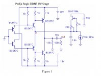
George traumatized me with this story of 2n2 cap for the JFET filtering at the outputt of the Pedja 's shematic because I use 1K R instead 1K5 (wasn't able to find 1k5 Rhopoint wirewound when I sourced the BOM). To wait for I planned to test some Vishays non Bulk I have on hand:
- CPF21K5000FKE14 (metal 2W, 1%)
-ACO1W1501JA100 (wirewound 1 W, 5%)
- RS01AK500FE12 (wirewound 1W, 1%)
I know the ww resistor is not the dreamed type of resistor for I/V but I use the Rohpoint as many due to the advices of T. Loesch...
By the way, about the // cap I use styren with tin foil, but has anyone tried silver MICA already ? It gives subjective very good result for some aop when small values are involved but never tried as filter I/V resistor ?
cheers
One friend said me, OT gives less bass, but I haven't this feeling based on the listening of my Philips SACD which can be electronically NOSed (it's a sort of DSP DAC, was famous in France 10 years ago for its good price and good sound and had been strongly tweaked by enthusiasts😛hilips DVP 5500 -SACD & DVD/CD player)
The bass are very good and have a lot of readness, sound "articulation" ! Certainly the help of the zobel ?
But with the opa shematic I posted above I use no output stage, because I trimm to zero mV the offset at working temperature : my pre is 47K inputt and has a DC inputt cap already).
For the few experience I have with buffer, most of the time the sound change with the supply, the caps, etc... Never ending story ! I'm not sure an opa 627 is better than an AD797 here ! YMMV of course !
Have you all read the old thread about "Best resistor for I/V" ? Does anyone remember what bulk resistor Peter Daniel used for its highly tweaked TDA1543 DAC ? It was a Caddock but I havent the ref in mind ?
George traumatized me with this story of 2n2 cap for the JFET filtering at the outputt of the Pedja 's shematic because I use 1K R instead 1K5 (wasn't able to find 1k5 Rhopoint wirewound when I sourced the BOM). To wait for I planned to test some Vishays non Bulk I have on hand:
- CPF21K5000FKE14 (metal 2W, 1%)
-ACO1W1501JA100 (wirewound 1 W, 5%)
- RS01AK500FE12 (wirewound 1W, 1%)
I know the ww resistor is not the dreamed type of resistor for I/V but I use the Rohpoint as many due to the advices of T. Loesch...
By the way, about the // cap I use styren with tin foil, but has anyone tried silver MICA already ? It gives subjective very good result for some aop when small values are involved but never tried as filter I/V resistor ?
cheers
Last edited:
That is a hard specification to find. Best way is likely with an oscilloscope and test generator. The 4n7 on the primary had to be changed to 3n3 with the LL1690, so not a hard and fast rule. Makes sense to experiment on the secondary side as well taking cable length into consideration. 8 mH is likely close enough as a start. I will be taking a short break from DIY due to another round of surgery. PM me if someone needs a response from me. 🙁 Probably won't be on here for a few weeks. 😱
I hope you have a swift recovery from the surgery my friend.
By the way, about the // cap I use styren with tin foil, but has anyone tried silver MICA already ? It gives subjective very good result for some aop when small values are involved but never tried as filter I/V resistor ?
cheers
I've tried many caps on I/V resistor, including silver mica (Soshin SE99). The mica sounds good, but I think the C0G/NP0 ceramic is even better. I was impressed by this little ceramic cap (just 10 cents each) as the SE99 is bulky and expensive.
I'm not a big fan of ceramic even class I but I never tested at this position, thanks for the tip. Does the inductance matters here ?
Ever tried styren or PPS ?
Ever tried styren or PPS ?
I'm not a big fan of ceramic even class I but I never tested at this position, thanks for the tip. Does the inductance matters here ?
Ever tried styren or PPS ?
In the latest issue of Linear Audio (vol 12) Groner Samuel and Scott Wurcer show that COG ceramics have lower distortion than polystyrene, and of course they sound excellent...
- Home
- Source & Line
- Digital Line Level
- Using the AD844 as an I/V