Hi.
I have a multi driver line arrays in (undersized) enclosures that I plan to use with subwoofer(s).
The drivers are a Tang Band 3" with Fs=120hz, Vas=1.6L, Qts=0.63, Qes=0.7, Xmax=1mm.
Each driver sees about 1.5L, and approx. Qtc=0.9, Fb=170hz, F3=140hz.
I was looking at putting a (largish) capacitor in series, not only for a high pass filter (sub goes up to 150Hz, using plate amp),
but also to extend the lower end of the full range (to mate better) and damp the peak at resonance.
I heard this is called a "Third Order Closed Box". I've searched extensively here, and on Google, and there is a range of
different opinions on this. One source (SB Acoustics) gave a formula that indicated a cap of 175-275uf, depending on whether the
"Qts" is the free-air value or the "system Q". Crossover calculators suggest about a 120uf just for high-pass duty. I have a large number of
high quality 100V non-polar electrolytics, as well as a large Poly motor-run cap, to parallel for the needed value.
Anyone here have experience with this type of application (i.e. combined augmentation and crossover with one series cap on small sealed box),
as opposed to deep bass augmentation of a large woofer?
Thanks,
-Charles
Yes, i used a high pass capacitor on a Peerless TC9FD18-08 (x-max 2.6 mm) in a very small variovent-ish/ closed 11 x 11 x 11 cm cube. F3 around 150 Hz. Q around 1.1. Don't remember the fine details, it is some time ago. Do remember they could play very, very loud. Simulates like 100 - 103 dB max spl in halfspace, this combination went beyond it's 30 Watt rating before reaching x-max. This does not mean you should put continous 30 Watt on these... just want to point out they could handle it, from an x-max point of view.
Don't be afraid of the high Q + added extra order, in such a small speaker, all the extra subjective volume / pressure is welcome.
Don't be afraid of the high Q + added extra order, in such a small speaker, all the extra subjective volume / pressure is welcome.
Last edited:
Hornresp can simulate this. Once you've got your enclosure, on the Acoustical Power tab, go Tools > Filter Wizard.
Set for passive (bottom-right drop-down menu) and you can see what's what.
I just ran the sim with an SB65 in a small closed box, and 400uF looks promising. It's worth noting that the extra LF output around the 3rd-order knee comes from presenting a lower impedance to the amplifier, and it will use more excursion from the driver. No free lunch.
Chris
The Tang Band 3's x-max of 1 mm, might be a little on the small side. Could you give the type nr of the Tang Band?
Hi.The Tang Band 3's x-max of 1 mm, might be a little on the small side. Could you give the type nr of the Tang Band?
Thanks for responding.
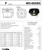
The drivers are Tang Band W3-565sc, and I'm using at least eight together in series/parallel (the approximately 12L enclosure will accommodate up to twelve W3's). Qtc is 0.9-1.1, depending on the number of drivers employed.
No active link could be found, but here's an image of the data sheet from Tang Band. The T/S parameters were listed in my original post.I cannot find this TB driver. Do you have a link?
Thanks for your help.
(And Happy New Year)
Attachments
should work wonderfull, if you give them each their own volumen, you are beyond to the SD of an 8 inch 🙂
Great 🙂should work wonderfull, if you give them each their own volumen, you are beyond to the SD of an 8 inch 🙂
What value series capacitor would you recommend for this driver in series-parallel group (for either 4 or 8 Ohms nominal)?
Thanks
What sort of amp are you using? If it uses an output cap, perhaps it could be modded? I'm not sure about non-polar electrolytics, and polarised ones with a constant DC bias could be an idea.
My amp is a direct-coupled, push-pull design with no series output cap. Another reason why I want to try this series cap on speaker input. I already have several non- polar caps to parallel, I just need to know how many microfarads.I would be happy to run a sim on AJ-Horn, but the pdf you linked misses the TSP 😉
From my O.P. (above)
"...The drivers are a Tang Band 3" with Fs=120hz, Vas=1.6L, Qms=6.88, Qts=0.63, Qes=0.7, Xmax=1mm.
If Each driver sees about 1.5L, then Qtc=0.9, Fb=170hz, F3=140hz...."
Hi, the program i use AJ-Horn, is very sensitive about the precise input of Le in mH, the resistance values at 1.000 and 10.000 Hz. This the response with Z1k = 8 Ohm and Z10K = 15 Ohm. I do not think the impedance graph in the pdf is realistic. Le in mH would be helpfull, to get closer to reality. This is the result in 1.5 liter with a 300uF capacitor in series, i took 0.5 Ohm series resistance. Half space 1 Watt.

...This the response with Z1k = 8 Ohm and Z10K = 15 Ohm. I do not think the impedance graph in the pdf is realistic. Le in mH would be helpfull, to get closer to reality...
"Le" is given as "0.08mH" in Tang Band data. I hope this helps. Is the 0.5ohms realistic? And shouldn't the series cap flatten the peak more at resonance in 3rd order closed box?
Last edited:
"Le" is given as "0.08mH" in Tang Band data. I hope this helps. Is the 0.5ohms realistic? Is 300uf for 4 or 8 ohm array net impedance?
And shouldn't the series cap flatten the peak more at resonance in 3rd order closed box?
And shouldn't the series cap flatten the peak more at resonance in 3rd order closed box?
Best curve fitting i could do with a RC element in the crossover for Re 6 Ohm and 0.08 mH Le. I used 2 drivers for the previous graph, forget about that one. Le was wrong too. Anyway, this is one of the W3-665SC drivers in 1.5 liter closed box, with a 330 uF capacitor in series, i scraped the series resistance:

Interesting, the x-max is hit before Vin = 1 Watt. Spl max is easy, every doubling of Sd gives 3dB extra. So Spl max would be + 9 dB for 8 drivers.
I don't know of a program that can simulate tubeamplifier reaction to impedance variations. Personally i would try to get rid of the peak at around 180 Hz. I used 0.5 Ohm series resistance because i reckoned there would be need for an LCR filter in series to tame the drivers from being overly bright. As in Cyburg's needle, with a comparable TB driver: https://www.acoustic-design-magazin.de/2017/07/01/needle_aufgewaermt/
Last edited:
Many thanks.
These (series/parallel=8ohms) drivers will be supplemented by two 12" subwoofers (plate amps up to 160hz, 12dB/octave).If the.W3's individual working volume is reduced to, say 1Liter each, how would that affect the response and SPL and is a different cap value indicated? Am concerned re xmax & distortion up to100db.
Thanks.
p.s. the power amps are solid state(only tube is in line buffer/preamp), active crossover used for subs.
Last edited:
Red = 1.5 liter volume + 330 uF, Black = 1.08 liter (Q1.0) + 300 uF. Both driven to x-max. The smaller volume gives a wee bit more max output. I don't think this will play well at 100dB, 2 drivers = +3 dB, 4 drivers + 6 dB, 8 drivers + 9dB. Let's asume x-max is linear performance, max spl linear would be 89 dB + 9 dB, so around 98 dB. Not counting baffle step, lcr correction, etc, etc. Also i am not very familiar with line array's, but do know there is such a thing as power taperng for line arrays. This could eat up more effiency.

Last edited:
For comparison, this is one TC9FD18-08 driven to x-max compared to one TB W3-665SC (in a Q 1.0 enclosure) driven to x-max. The varioventish + series uF enclosure is a sketch, not worked out very well, but you can clearly see x-max is your friend.

- Home
- Loudspeakers
- Full Range
- Using Series capacitor for Bass on Full Range Driver