smoking-amp said:Fixed
On the Blumlein scheme, I wouldn't think it would be any more problem than parafeed. Just have to be careful where the resonance falls so it doesn't get excited. Can probably make it a damped resonance as well. But if it can be gotten rid of ..... one less artifact.
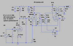
...and a Vbe multiplier instead of Zener.
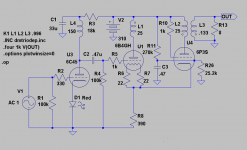
R1 pulls up and the tube plate pulls down. Could put a CCS in place of R1 for better accuracy. Q2 acts as a constant Beta current multiplier for the tube plate. So the plate is lightly loaded by base current. The voltage drops on resistors R3 and Rs should roughly sum to a constant ,set by the D1 zener. (Michael has been using this type of setup lately, ie, the old model #3 I think)
So the current from the Mosfet should be roughly complementary to the current from the bipolar. So roughly "anti-triode" behavior from Q1 and magnified triode behavior from Q2. The screen connection just acts for "triode" feedback to keep the tube happy with its Mu (g2/g1) requirement. So the final output should be about Mu times the input. Since the screen always draws some current, no need for a pull down resistor there. Also, since the screen tracks the plate voltage pretty closely, it should draw fairly constant current (or actually a constant fraction of the plate current).
"...and a Vbe multiplier instead of Zener."
Yep, that would surely give better thermal tracking for the SS parts. Although the Rs resistor in the source should make it fairly stable too.
Shoog, you got it all figured out, it can be looked upon as a parafeed cap. The reason for me was to use as small cap as possible to minimize cost of a film/oil. The amp will not be used with feedback or extremely low frequencies.
SmokingAmp, about distortion reduction we are talkin about SETOR-II (single 6B4G), not SEPTOR (parallelled 6B4G). By the way, distortion is not significantly lowered by parallelling two triodes if, as in this case, load is lowered from 6 to 3k. And why ruin a good sounding amp and linear amp with NFB?????
If you want to loose the cathode-cap this is the way to go! Current-balance is adjusted through R26. What remains is to find a way of auto-adjustment it like with the currentmirror used in SETOR. You clever guys will solve that, won´t you?
Attachments
There must be a gestalt mind after all.
I have a SS version of your first schematic on the bench now for
testing. I couldn't find the resistor value I needed to finish last
night (attached).
I like your anode voltage servo #1, but #2 may be a challenge building
the floating supply.
I'm currently trying to eliminate the current tracking time constant
altogether, but that probably means either using a small-gapped
OPT or using yet another winding on the OPT to cancel only the
residual and large signal offset between triode and slave. Hmmm...
Cheers!
Attachments
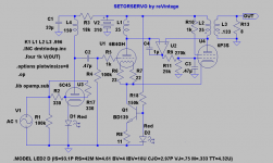
revintage said:Or like this with the OP-amp +/-15V centered around ca 305V?
Ooh... make sure your safety glasses are on when you power this one up!
;-)
Michael
Didn´t you notice that I questioned if it would work😉?
I am currently waiting for the sandman to come with the optimal solution.
Maybe one could do something with an optocoupler to make things a little less hazardous 😀?
I am currently waiting for the sandman to come with the optimal solution.
Maybe one could do something with an optocoupler to make things a little less hazardous 😀?
Visited hoktuna yesterday for some listening and measuring of the SETOR.
Compared to what he previously used to drive his mid and treble this was a total makeover! Airy with depth and separation that wasn´t there before.
Despite the listening impression it didn´t measure to well. Below 100hz the sine was deformed and above 15k the level fell with -3dB at ca 18khz 😕. Aso square wave showed considerable ringing in the midband and rounded of flankes above 10KHz 🙁 .
We where a little dissapointed until we measured at the output of the driver and found the same deformation there😱 .
As this is a budget project we had used a Hammond 156C as choke load and this must have ruined the outer ends of the spectrum. So we will change places with the choke and the 18k resistor and do some new tests Sunday. Another option to be tried is an el Cheapo CCS with a single DN2540 as anode load.
In all this was a postive inital test of the SETOR😎.
Compared to what he previously used to drive his mid and treble this was a total makeover! Airy with depth and separation that wasn´t there before.
Despite the listening impression it didn´t measure to well. Below 100hz the sine was deformed and above 15k the level fell with -3dB at ca 18khz 😕. Aso square wave showed considerable ringing in the midband and rounded of flankes above 10KHz 🙁 .
We where a little dissapointed until we measured at the output of the driver and found the same deformation there😱 .
As this is a budget project we had used a Hammond 156C
as choke load and this must have ruined the outer ends of the spectrum. So we will change places with the choke and the 18k resistor and do some new tests Sunday. Another option to be tried is an el Cheapo CCS with a single DN2540 as anode load.In all this was a postive inital test of the SETOR😎.
Hi Lars and Hoktuna,
I would definitely go with the DN2540 and 2 1/8 watt resistors,
replacing the choke, 18K dropper, and the filter cap. You can do it once
and then forget about it.
I have just started playing with 6S45pi and I like about 15mA standing
current and a 2V to 2.2 volts LED on the cathode. This will drive about
200V P-P, enough for a 300B.
Cheers,
Michael
Hi Revintage,
Some food for thought, really not too worried about the driver as it will be constantly running grid current. Driver could even be SS transformer coupled. I want 2 big bottles up there, fantastic visual impact and with 150 watts of filament power at least 10W of impeccable sound.
A bit miffed that it cant be done with 100V HT. Anyone understand why 833 characteristics look like a classic pentode?
Seriously, triode chars are all vertical while these are all horizontal.
Mike.
Maybe I should add that I use 813s where others use a DL96, ie even lower HT like 25V for RF etc.
Mike.
How about a simple desktop regen MW RX (tuner) using an 833 with all of it running on 10V dc inc the filament supply.
Mike.
Mike.
How about a simple desktop regen MW RX (tuner) using an 833 with all of it running on 10V dc inc the filament supply.
Mike.
Will use EL519/6KG6 instead of 6550 as anti-triode in my SEPTORS with parallelled 6B4Gs. Sims so much better, must be the high Gm. Will take some photos tomorrow when I have mounted the magnoval sockets and topcaps.
Yesterday i move the 150H choke and hook up the scope.
The sine wave now looking good below 100 hz🙂
The sine wave now looking good below 100 hz🙂
Hello,
Time to move this thread forwards! 😀
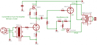
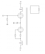
This idea came to my mind of output toroid current compensation. For the input signal it acts like a SE amp. It works with split supply. Capacitor decouples the signal at the middle. No need for transistor current mirrors 🙂 No need for current tracking, same current goes through both windings. I think some of those 115V + 115V mains toroids works fine here as in my previous protos as well.
What do you think? 😀
- Elias
Time to move this thread forwards! 😀
This idea came to my mind of output toroid current compensation. For the input signal it acts like a SE amp. It works with split supply. Capacitor decouples the signal at the middle. No need for transistor current mirrors 🙂 No need for current tracking, same current goes through both windings. I think some of those 115V + 115V mains toroids works fine here as in my previous protos as well.
What do you think? 😀
- Elias
Attachments
Sorry to resurrect such an old thread - but I have a question for Revintage.
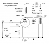
I am toying with the idea of building a nice little SPUD amp using a E55L. When researching I came across this design of yours
http://www.diyaudio.com/forums/tube...former-output-transformer-12.html#post1617108
very interesting. I only just understood after some thinking how its DC stable. Is this still a workable design or did it develop issues in use.
Could it be adapted to use a E55L.
Shoog
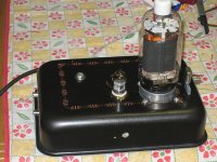
Pulling up an old thread - I read through it all and while the PP designs don't fit my needs, there are some good observations regarding parafeed. I just built a working headphone amp using a 60VA mains toroid 230v/12+12 (in series) to give 9.6:1 step-down. Sound is excellent but I may be getting some kind of ringing or oscillation, or the headphones (K701) are peaky in the treble. Whatever. Anyway, I have some questions:
1. For a headphone amp what would be the difference between a 15VA and a 60VA (or 100VA) transformer regarding primary inductance and overall sound quality?
2. Tell me more about ringing and how to avoid it - does VA play a part here?
3. Interesting observation that you should reverse the primaries to test if it sounds better.
Any other tips and traps for a headphone stage in parafeed?
Attachments
Posting after reading the first page of the thread, though I'm sure I have read more in the past...
I have been using very small 1.6VA to 5VA PC mount toroid as OPT for a small headphone amplifier, parallel feed (max output about 55mW)
My results have been pretty good, in testing the transformers had a good bandwidth, 10Hz to about 60kHz -3dB.
But that was when using only a single primary winding, and single secondary winding, all other windings open circuit (115+115: 15+15)
Perhaps a useful tip for someone? Using in this way the turns ratio remains the same, but leakage capacitance (I guess) is reduced, inductance is reduced. Using these toriods in particular, there was no issue with LF response, even driving with 20k source impedance; the effects were almost all confined to HF response.
Last edited:
Thanks for the reply. Which are these small PC mount toroids? The ones in a flat blue plastic case or what?
What advantages in using only a single winding for primary and secondary?
What advantages in using only a single winding for primary and secondary?
- Home
- Amplifiers
- Tubes / Valves
- Using mains transformer as output transformer