There are several factors to consider.
First, mains transformers are not audio output transformers. THey are invariably wound with the primary first, possibly in two stages for a split primary; then the secondary. That type of construction does not give good coupling at high frequencies - the problem it gives rise to is leakage inductance. Instead, an audio transformer is, or should be, wound in layers or bifilar, whichever is more appropriate (bifilar is not always the best), so that there is tight coupling between the primary and secondary.
The other issue here is that a large core needs a lot of power (relatively speaking) to transverse the magnetic BH loop. Therefore a 60VA is not appropriate for, say, 1W output as it might need 1W just to magnetise the core. Use a smaller core for lower power.
Previous posts have addressed the issue of DC current - this has to be avoided.
But, toroidals should be better than EI cores as the secondary is wound over the whole of the primary (most EI cores for mains use split bobbins which separate the primary and secondary. OK for LF but not HF). (Specifically wound audio designs layer the primary and secondaries even in a split bobbin). Generally toproidals can use thinner steel (to reduce eddy currents) which is particularly important for audio.
I suspect your ringing is due to leakage inductance. You might try adding negative feedback to reduce it.
andyjevans,
Do you have bench test setup for the amp - in particular something like a soundcard spectrum analyser or scope so that you can do a frequency sweep to see how flat your response is, and if there is any peaking above the audio range?
Imho you really need to do some testing and post some results, along with a schematic and some photos.
Andy,
The toroid are Nuovo Talema PC mount toroid, available in the UK from RS components for the princely sum of £5.
I have also used the RS branded OEM version of the Nuovo Talema, with similar results, IIRC the ratio suited the circuit better with respect to THD.
P/N 124-3843 for the 115/115:15/15 which i use. This gives N= 6 roughly, and measured impedance of around 10k, across the audio band.
For a higher ratio, like you're using something like the 115/115:9/9 RS part 173-0111 may suit better.
Tbh it's a bit of a cr@pshoot, I bought two different secondary voltage toroid as I thought that I would improve performance, or that they were better suited. I was wrong!
I.e. the 115:15 has N=6, measured Z of 10k, and simple Z ratio of about 12k, when loaded with 330R headphones
andyjevans,
Do you have bench test setup for the amp - in particular something like a soundcard spectrum analyser or scope so that you can do a frequency sweep to see how flat your response is, and if there is any peaking above the audio range?
Imho you really need to do some testing and post some results, along with a schematic and some photos.
Yes - you're absolutely right. I need a test setup, but unfortunately I don't have one. I have a scope but never studied how to use it, something I should correct. I think I have all the necessary parts for the scope, what I need is an hour's tutorial which right now would have to be over the internet. I keep putting it off since I put time into actual builds, but in cases like this I really would need to measure the results to see if there is oscillation or ringing. I might be able to scare up some photos.
Thanks mondogenerator for the info - very useful. Are you saying that the small VA toroids might sound better for a headphone than the 60VA one I'm using? I have some smaller blue PCB ones I could try - they're Clairtronic but look exactly like the Talema ones. They're more like £15 from RS these days.
Stray Capacitance interacting with the inductance will cause high frequency ringing, this will manifest as a 3-6db peak out at about 50khz which is very fatiguing to listen to. This can be bad enough to saturate the core and cause low frequency drop off as well as peaky high frequency response. Because of the way they are wound stray capacitance will be significantly different with the primaries wired in one direction as opposed to the other - so a test rig signal generator and scope will reveal which primary polarity has the lowest stray capacitance. Failing this extended listening with one polarity and then the other will reveal that one is more fatiguing than the other.
All the toroids I have come across have bifilar primary windings in a spiral out from the core, with the secondaries wound over the top.
I found that the capacitance is sufficiently high either way that there will always be a certain amount of high frequency ringing. Since you are using them for headphone amps you have power to burn. The best way to kill the ringing is to load the secondary down. Something like double the headphone impedance across the secondary should smooth things out significantly at no penalty to power output.
Smaller VA is generally better 5VA would be best for a headphone amp.
Shoog
Last edited:
Hello Shoog - I was hoping you'd join the thread. So I should try out smaller VA transformers. I can do that. And reverse the primaries - can do that too.
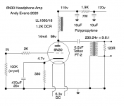
I've put a 120R resistor across the output in the attached circuit. My K701 cans are 62R. Does that sound OK? I'll still get the same impedance matching for the cans?
I've put a 120R resistor across the output in the attached circuit. My K701 cans are 62R. Does that sound OK? I'll still get the same impedance matching for the cans?
Attachments
Hello Shoog - I was hoping you'd join the thread. So I should try out smaller VA transformers. I can do that. And reverse the primaries - can do that too.
I've put a 120R resistor across the output in the attached circuit. My K701 cans are 62R. Does that sound OK? I'll still get the same impedance matching for the cans?
Exact impedance matching in this situation is not at all critical.
Report back your observations.
Shoog
OK - preliminary observations....
- it sounded better without the 120R resistors, better timbre to instruments and a fuller sound. The resistors added a subtle "closed in" effect, and also sound was quieter.
- I do hear a difference inverting the primaries. The better side is like the above difference better timbre to instruments and a fuller more natural sound.
This is with smaller 25VA toroids, the encapsulated blue plastic type like the Talema ones mentioned above. I have a vague feeling that the 60VA toroids sounded better but could be wrong. I'll swap those back in and switch primaries as well and report back.
I suspect that the oscillations or ringing is in the tube socket. Will try some ferrite beads if I can find them and report back on that. I really need a scope for this - it would be so much easier. Must teach myself how to use it. Anyway, more listening tests to come.
Be careful, the "better timbre" may turn out to be the dreaded ringing and only extended listening would reveal its fatiguing quality. I have seen people report ringing as more "air" before. Ultimately its a matter of taste but be careful of quick listening impressions.
You can use a computer sound card as a sine wave source and get it to sweep the frequencies - but many only extend out to 20khz which will not give you much useful information.
Shoog
You can use a computer sound card as a sine wave source and get it to sweep the frequencies - but many only extend out to 20khz which will not give you much useful information.
Shoog
Last edited:
Update - switched back to the 60VA transformer and I prefer it. Not by much but the sound is a little fuller and more natural. I haven't tried switching the primaries yet. Will do a bit more listening as it is now to see if my feelings are correct. This is my initial setup before all the changes, though I have yet to try switching primaries. Seems to run counter to the idea of using a smaller VA and adding resistors. I'm new to all this idea of mains transformers as OPTs, so can't be of much help other than giving some subjective feedback. Thanks for all the help so far - I needed to try out these alternatives.
I also have a pair of LL1689/PPs that I'll swap in at some point. They should hopefully not ring and I'll be curious to see the difference in sound quality.
I also have a pair of LL1689/PPs that I'll swap in at some point. They should hopefully not ring and I'll be curious to see the difference in sound quality.
Its an old topic i know but you can use mains transformers as output transformers also in single ended.I made a cracking set set of OPT some years ago for SE el84 huge transformers actualy.sounded like very expensive ones.first i found the transformers with the right impedance ratio .Then i read that for SE you must have air gaps in the core of the E and Is so i stripped all of them out and glued thin cardboard to every one,and packed them all back in,its tricky to get it tight and you have a few left over.but it works 100%.
Few amateurs take this into consideration.I'm guessing you haven't measured the primary inductance?
A fairly typical SET OPT number, but it's not actually good.10H seems typical since the opt is gapped....
chris & bob
Not sure where you actually put your air gap. Surely not between EI layers?
All you needed to do was to collect all the E plates together and all the I's and use a thin spacer between the two.
If, as I think you may have done, put the gaps between EI plates, these are not in the magnetic path as you may have EI plates in contact. All you seem to have done is reduce the magnetic core area. Hope I'm wrong in that interpretation.
AS mentioned elsewhere if the mains transformer was on a split bobbin that is not good for audio. Hope your transformers were at least wound with secondary on top of primary.
A fairly typical SET OPT number, but it's not actually good.
it's not, compared to ungapped pp opt's that has inductance in the 100's of henries...
Yeah, that's sort of what I meant. I've never used an untapped PP OPT except on a couple of occasions where they were paraphase, but even with a modest gap to account for OP tube imbalances are still much, much higher than a SET. Instead of measuring distortion at 1kHz and claiming SETs aren't too bad, try it at the bottom of the passband. I was commenting on this about the same time as the Y2K scare on RAHE.it's not, compared to ungapped pp opt's that has inductance in the 100's of henries...
Efficient speakers? They will be driving 105 dB/W horns, ultimately. It’s an ALL TUBE PA rig. Kind of a bucket list project. I already have a 30kW SS PA rig. Been keeping the “expense” down by using off the shelf OPT iron, home brew PT iron, and $3-10 tubes, and collecting stuff over a few years to spread it out. I don't even want to think about what it would cost to buy “real” custom iron and KT88’s. Enough to say “**** it”, that’s for sure.
- Home
- Amplifiers
- Tubes / Valves
- Using mains transformer as output transformer