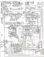
I picked up a nice looking old 70's Kenwood that was missing parts, so I retrofitted it with a new PS/amp/preamp and I'm trying to come up with the best way to power the legacy tuner/phono stages in the unit. I'm very tight on space so would prefer not to add another transformer.
3 voltages are needed, +28v, -19v, and 13.5v.
I was considering an lm317HV/lm337 connected to the main +-40V supply to derive the +28v & -19v.
For the lm337 I saw this thread which uses a zener across the input-output so you can use it with higher voltages.
For the +13.5v I was considering using the positive half of the preamp supply but wondering if pulling from half the supply is a bad idea.
I'd like to keep the legacy components functional, even though realistically they will probably rarely if ever be used.
Attachments
Be careful about the power dissipated in your regulator ICs. Power is equal to (Vin - Vout)/Iout - - - - - and if you're using regulators with a big metal tab sticking out of a TO-220 package, you want regulator dissipation to be less than 0.67 watts (less than 2/3 of a watt) for each regulator. If you're using scrawny little TO-92 "transistor package" regulators, you want regulator dissipation to be less than 0.33 watts (less than 1/3 of a watt) for each regulator. Otherwise you're in danger of overheating your regulators and all nearby components.
One way to reduce regulator dissipation is to add more components and arrange the circuit design so that these new components dissipate some of the power. The most obvious example would be "5 watt zener diodes". Now to get from -40V to -19V_regulated, you could have
-40V ----> anode of 1N5354B (17V 5W) ----> diode body ----> cathode of 1N5354B {now at -23V !!} ----> input of LM337 regulator ----> output of regulator (-19V regulated)
The LM337 dissipates 4V/Iout and the zener diode dissipates 17V/Iout. Voila! Regulator power dissipation with zener is 19% of regulator power dissipation without zener!!!
Of course you do have to pay for new components (zener diodes) and you have to locate them somewhere that won't fry nearby parts.

Yes. I picked up a couple of these. https://www.ebay.com/itm/394727553148can the regulators be mounted on a heatsink if needed
I got the diy version so it's easier to modify and swap the fake Nichicon's. The heatsinks are fairly large. Worst case there might be room on the main amp heatsink. I would prefer a design that doesn't require that much dissipation though, if possible.
So similar to this only inverted?40V ----> anode of 1N5354B (17V 5W) ----> diode body ----> cathode of 1N5354B {now at -23V !!} ---
Attachments

Ooof, thanks for the correction, Marcel! Yes in post #2 there is an error. The correct equation is: Power = (Vin-Vout)*Iout , precisely as you mentioned.
And if the "main +-40V supplies" change 1% when the AC mains voltage changes 1%, that must be included in the -19V regulator scheme as well. Same goes for any ripple voltages on the "main +-40V supplies" . Precisely as you mentioned.
And if the "main +-40V supplies" change 1% when the AC mains voltage changes 1%, that must be included in the -19V regulator scheme as well. Same goes for any ripple voltages on the "main +-40V supplies" . Precisely as you mentioned.
Low currents. First step is to know how much.
Little space.
I would use shunt regulators. 3 x ( TL431 + 3 resistors ). See data sheet.
Current throught TL431 must be > 1mA
Little space.
I would use shunt regulators. 3 x ( TL431 + 3 resistors ). See data sheet.
Current throught TL431 must be > 1mA
So similar to this only inverted?
That's not what Mark described, Mark just suggested dropping some of the voltage over Zener diodes to reduce regulator dissipation. Whether that is necessary is unclear, though.
As the -40 V will have a tolerance and as the LM337HV doesn't appear be available (or exist?), I think dropping at least 5 V across a big Zener for the negative supply would be a good idea. Otherwise you have to figure out what voltage comes up how quickly to ensure you don't exceed the regulator ratings.
For the positive supply, you can simply use an LM317HV, like you already intended to.
The 35 V capacitors at the inputs of your regulator board obviously have to be replaced with ones of 50 V or 63 V working voltage. 100 uF should be more than enough when you only use them as local decoupling, rather than smoothing capacitors.
OK, thanks, that's a nice simple solution. I only need -19V so maybe a 10-15v zener would be better? Guessing under 150mA load so a 5W would still be more than enough. Regarding the caps, yes I was planning on 63V if they fit.dropping at least 5 V across a big Zener
Last edited:
you can always attach the regulators to the chassis if it is possible. The chassis will be the heat sink.
DC/DC (buck) converters. I do not like them much... but, in this case, they might be just right. Stack them on top of each other. They are small and almost have no heat dissipation. You can follow with a (or a combination of...) Zener diode(s) final regulation stage, after a DC/DC converter... if you can't get the exact voltage you need.
... would this do the job? The good thing about these is that your -19V need will also be met easily...
https://www.amazon.com.au/Supply-Co...keywords=buck+converter&qid=1724323984&sr=8-5
... would this do the job? The good thing about these is that your -19V need will also be met easily...
https://www.amazon.com.au/Supply-Co...keywords=buck+converter&qid=1724323984&sr=8-5
Last edited:
I thought about those but the tuner would likely be useless from the RFI they generate.DC/DC (buck) converters
You don't need the HV devices. The LM317 and LM337 are floating regulators. They only care about the voltage difference from input to output, which can be up to 40 V.
So the LM317 and LM337 will be fine with ±40 V input and the output voltages mentioned.
As Mark points out, you do need to watch the amount of power dissipated in these devices. Attach them to a heat sink (with appropriate thermal pads and mounting hardware) if necessary.
Tom
So the LM317 and LM337 will be fine with ±40 V input and the output voltages mentioned.
As Mark points out, you do need to watch the amount of power dissipated in these devices. Attach them to a heat sink (with appropriate thermal pads and mounting hardware) if necessary.
Tom
You don't need the HV devices. The LM317 and LM337 are floating regulators. They only care about the voltage difference from input to output, which can be up to 40 V.
Do you want to think about this for a sec...??
I shudder at the thought of putting switchers inside a hi-fi anything.
I like the 337, (and I would suggest 338 instead of 317 as it matches the 337's 5A output capacity if properly heat-sinked), but for your power levels the 317 is fine. Lower noise than fixed regulators. Extreme_Boky is right, they are floating. ADJ pin is only 1.25V below/above output, and IN/OUT have no idea where they are w/r/t GND, only the out to in differential matters. Watch input filter capacitor voltages as mentioned.
Using zeners or other diodes to dissipate heat works, but I don't think it's necessary if the regulator is cooled properly. I'd just heat sink them to the chassis somewhere, with the proper mica insulators and thermal paste. They can be several inches away if you add some 0.1uF ceramic caps from in to GND, and out to GND, and I often use a 10uF electrolytic from ADJ to GND. The heat sinks on the pre-made boards look a little small, but again we have no idea the power levels you need to generate.
Be sure to add protection diodes (like basic 1N400x) to both ADJ and OUT. On the positive regulator add one from ADJ to OUT (with band facing OUT) and one from IN to OUT with the band facing IN. For the negative regulator add one from ADJ to OUT with band facing ADJ, and IN to OUT with band facing OUT. This will prevent the regulators from being damaged when you turn the unit off and the capacitors discharge back through the supply. A great design example of the basic approach for both positive and negative supply are on Rod Elliott's ESD project 05D website.
BTW- I hope the regulator IC's that came with the DIY kit are authentic. I am so paranoid about fakes now.
Last edited:
You don't need the HV devices. The LM317 and LM337 are floating regulators. They only care about the voltage difference from input to output, which can be up to 40 V.
So the LM317 and LM337 will be fine with ±40 V input and the output voltages mentioned.
True, but you have to analyse what happens at start-up then: how fast does the input voltage rise, how fast does the output voltage rise and does the difference between them stay small enough at all times, even when the mains voltage is 10 % above nominal and the amplifier is switched on at the most unfavourable phase of the mains? There is a good chance that it will be if the reference pin isn't decoupled/filtered, but I'm usually too lazy to analyse it properly, hence my preference for HV devices.
Last edited:
This is a board delverboy intends to use according to post #4:

If any of the 100 uF electrolytics decouple the ADJ pins, not placing them will help to keep the peak input-to-output voltage at start-up low, at the expense of more noise and worse ripple rejection.
If any of the 100 uF electrolytics decouple the ADJ pins, not placing them will help to keep the peak input-to-output voltage at start-up low, at the expense of more noise and worse ripple rejection.
Consider reading the data sheet.Do you want to think about this for a sec...??
Tom
- Home
- Amplifiers
- Power Supplies
- Using LM317/337 to power low current stages off of main +-40V supply