nzoomed,
Since your transformer has 2 secondaries, no less and no more . . .
For your two windings that are nominal 2 Ohms . . .
Two windings in series are 8 Ohms (series in-phase)
Two windings in parallel are 2 Ohms (they have to be in-phase).
I would try using the 8 Ohm connection for 8 and 16 Ohm speakers.
I would try using the 2 Ohm connection for 4 Ohm speakers (or two 8 Ohm speakers in parallel.
I would try comparing both the 8 Ohm connection, and the 2 Ohm connection for 6 Ohm speakers.
nzoomed::
Are the transformers from vintage NZ manufacture? I have the Beacon book which shows the chart for connecting their multiple 2-ohm secondaries if you need it
Are the transformers from vintage NZ manufacture? I have the Beacon book which shows the chart for connecting their multiple 2-ohm secondaries if you need it
Whenever possible, use all the secondary windings.
I have some output transformers that have 4 each 1 Ohm windings.
Using the proper connections, and all the secondaries, I can get the following output impedances:
1 Ohm
4 Ohm
9 Ohm
16 Ohm
Connecting it the right way is a little tricky, but all 4 windings are used for all of the above impedances.
Perhaps it might be better to aim at equal »mistakes« for any of these nominal impedances, not for just the 8 Ω one. This would require 0.9428 Ω packages.
Best regards!
I doubt that a true 8 Ohm speaker on a 9 Ohm tap would be a problem.
However, an 8 Ohm speaker that is actually only 5 to 6 Ohms at several areas of the frequency range, would be better off by connecting it to a 4 Ohm tap.
Precision secondary windings of 0.9428 Ohms, requires not only precision in the number of secondary turns, and precision in the number of the primary turns.
But . . . it also requires precision in the DCR of the primary and the DCR of the secondary windings.
A dog chasing it's tail, all for hardly any difference in performance.
I actually consider the transformers I have to be very flexible for matching to different speaker loads.
Also, the windings are interleaved, that is a good thing.
Yes, it is more trouble to have all those extra windings, and more trouble to connect for the desired impedance.
I am not a fan of using switches to make the impedance change easier.
Whenever possible, use all the secondary windings.
I have some output transformers that have 4 each 1 Ohm windings.
Using the proper connections, and all the secondaries, I can get the following output impedances:
1 Ohm
4 Ohm
9 Ohm
16 Ohm
Connecting it the right way is a little tricky, but all 4 windings are used for all of the above impedances.
Devised by Malcolm Watts
It certainly looks like it gets complicated with the switching method quite fast!
FWIW, Im not too worried, since I will likely only be using an 8 ohm load most of the time with this, I doubt I will even use 4 or 16 ohm speakers.
I do have a pair of rola 12px which are12 inch full range speakers and 5 ohms, I dont know if ill ever use them as they need a huge cabinet, but then have been told they will work fine in an open baffle configuration, what I like about them is they are very efficient drivers.
nzoomed,
Since your transformer has 2 secondaries, no less and no more . . .
For your two windings that are nominal 2 Ohms . . .
Two windings in series are 8 Ohms (series in-phase)
Two windings in parallel are 2 Ohms (they have to be in-phase).
I would try using the 8 Ohm connection for 8 and 16 Ohm speakers.
I would try using the 2 Ohm connection for 4 Ohm speakers (or two 8 Ohm speakers in parallel.
I would try comparing both the 8 Ohm connection, and the 2 Ohm connection for 6 Ohm speakers.
nzoomed::
Are the transformers from vintage NZ manufacture? I have the Beacon book which shows the chart for connecting their multiple 2-ohm secondaries if you need it
I dont have any OT yet, this whole multiple secondary idea I was talking about earlier was what an old fella from Australia told me to do.
It sounds like it is actually a thing, but how he described it to me in regards to wiring the secondary is wrong.
I think I might have a digital copy of the same beacon book you are describing.
I acquired a bunch of winding equipment and wire from a transformer manufacturer that shut shop some years ago, Im hoping to have a crack and get some made myself for the challenge. Got to blow the dust off alot of this stuff and work out how this winder works.
Last edited:
Use an accurate DMM to read the DCR of your 12 Inch full range speakers.
(my DMM has a 50 Ohm range, I short the leads, push the Cal buton, and it Auto-calibrates).
Then I read the driver DCR.
A bare driver has a cone resonance.
The minimum impedance value of a bare driver often reaches down to the DCR in the real low frequency range (well below the driver cone resonance); and then again in the midrange frequencies well above the driver cone resonance, but before the voice coil inductance causes a rise of the driver impedance as the frequency goes up.
Last edited:
Use an accurate DMM to read the DCR of your 12 Inch full range speakers.
(my DMM has a 50 Ohm range, I short the leads, push the Cal buton, and it Auto-calibrates).
Then I read the driver DCR.
A bare driver has a cone resonance.
The minimum impedance value of a bare driver often reaches down to the DCR in the real low frequency range (well below the driver cone resonance); and then again in the midrange frequencies well above the driver cone resonance, but before the voice coil inductance causes a rise of the driver impedance as the frequency goes up.
From memory they measured around 7 ohms, but I now have since got a better meter I can test with again.
The impedance is essentially the resistance at a given frequency. Since the speaker has to take a range of frequencys, do the manufacturers typically take an average over a given range?
I will take another measurement today when i pull them out. Its probably worth making the transformers suit them if they are decent enough drivers, even for the sake of testing them out.
I susepect they should have a fairly high efficiency.
1. The drivers should have a data sheet with the impedance curve versus frequency in free air (no enclosure).
Otherwise you are at the mercy of the manufacturer's marketing department.
They can call the impedance whatever they want, nominal is just that, no two judges will call it the same way.
A single full range driver that is in free air (no enclosure), might be called a nominal 8 Ohm driver.
At 20Hz it will probably be equal to the voice coil DCR. But at the cone resonance it might be 20 Ohms or even 100 Ohms. And at mid frequencies it might again be equal to the DCR, and then increasing at high frequencies to be 20 Ohms at 20kHz.
What would you call the average of that?
You begin to see the problem.
Putting the driver in a very large area flat open baffle; or an empty closed box; or a very heavily stuffed closed box; or a ported box; or a transmission line enclosure; or on an extremely large horn; will give different impedance results for each.
2. The impedance of a bare bones driver (no crossover components) can never be lower than the DCR.
The DCR is the resistance of the voice coil, it is 'in-series' with the other aspects of the driver.
Other aspects:
Cone resonance, the driver creates a back EMF (reverse voltage) that raises the impedance at resonance.
The voice coil is an inductor. The impedance of an inductor increases as the frequency gets higher.
An enclosure can change the resonant frequency, and reduce the impedance at resonance.
A ported enclosure changes the impedance, so that there are two raised impedance resonances, they are on either side of the original cone resonant frequency; you get 2 impedance peaks instead of one.
3. After looking on the web at the same or similar drivers, the free air impedance at 400Hz may be about 15 Ohms.
Different enclosures can change this.
Last edited:
Nominal impedance may be in the valley around 400Hz; for simple speakers this is often best.
It is generally agreed that higher peaks/rises are not a problem for transistor amps.
Multi-way speakers which abuse the crossover to bring up output in an overlap area may have LOW impedance dips in narrow bands. This can embarrass otherwise able amplifiers.
It is generally agreed that higher peaks/rises are not a problem for transistor amps.
Multi-way speakers which abuse the crossover to bring up output in an overlap area may have LOW impedance dips in narrow bands. This can embarrass otherwise able amplifiers.
1. The drivers should have a data sheet with the impedance curve versus frequency in free air (no enclosure).
Otherwise you are at the mercy of the manufacturer's marketing department.
They can call the impedance whatever they want, nominal is just that, no two judges will call it the same way.
A single full range driver that is in free air (no enclosure), might be called a nominal 8 Ohm driver.
At 20Hz it will probably be equal to the voice coil DCR. But at the cone resonance it might be 20 Ohms or even 100 Ohms. And at mid frequencies it might again be equal to the DCR, and then increasing at high frequencies to be 20 Ohms at 20kHz.
What would you call the average of that?
You begin to see the problem.
Putting the driver in a very large area flat open baffle; or an empty closed box; or a very heavily stuffed closed box; or a ported box; or a transmission line enclosure; or on an extremely large horn; will give different impedance results for each.
2. The impedance of a bare bones driver (no crossover components) can never be lower than the DCR.
The DCR is the resistance of the voice coil, it is 'in-series' with the other aspects of the driver.
Other aspects:
Cone resonance, the driver creates a back EMF (reverse voltage) that raises the impedance at resonance.
The voice coil is an inductor. The impedance of an inductor increases as the frequency gets higher.
An enclosure can change the resonant frequency, and reduce the impedance at resonance.
A ported enclosure changes the impedance, so that there are two raised impedance resonances, they are on either side of the original cone resonant frequency; you get 2 impedance peaks instead of one.
3. After looking on the web at the same or similar drivers, the free air impedance at 400Hz may be about 15 Ohms.
Different enclosures can change this.
Interesting that the impedance changes depending on the enclosure, im assuming this has to do with the interaction of the magnet depending on how much air resistance there is on the cone?
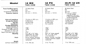
This is all the info I can find on these drivers.
Your right, its 15 ohms according to this.
That could make winding the transformer complex if i want to optimize it for these drivers, I think long term I will stick with 8 ohms however, as these are only rated at 20 watts, and my 8 ohm speakers are rated higher.
Attachments
- Home
- Amplifiers
- Tubes / Valves
- Using 807s in a mullard 5-20 circuit