Can you share the new firmware? I found a September 24th version with the original link but now it doesn't seem to be there. I did try that Sept 24 driver when it was there but still had the driver error when I2S input was selected. I have tried it with an ADAU1467 board SDATA output connected as I2S input to the York so the ADAU generates all of the signals - BCLK, WS and SD but the York board still has the driver error.It was a mistake in firmware, sorry about that. Now it is fixed and you can update the firmware using the tool.
This is not added yet, will work on this tomorrow.
This is fixed, please check PM for new config tool version.
It is published, to update module please open config tool, go to 'about' tab and click 'check for updates':Can you share the new firmware?
(you need internet connection)
After update firmware version should be 2.1 (build 1180) - this is the latest published, which has fix I mentioned.
I'll send you PM with relevant document and instructions regarding that.I have tried it with an ADAU1467 board SDATA output connected as I2S input to the York so the ADAU generates all of the signals
Couple of times I've got comments that this module lacks isolation. Perhaps it's time to fix it 🙂

It is not final. I've included HW to to support as many output configurations as possible including aux signals (plug, mute, dsd etc) as well as isolation of the I2C bus. Both external or onboard master clock are supported.
The "3.3v" on 20 pin header became input in this case, to supply isolated side. Actually it can be 3.3-5.5V.
Presence of this supply can be detected and used to enable MCU's USB.

The project is well advanced!
The PCB is ready, and even a configuration tool.👏
i2s inputs! I like that 😀
Allow me a few questions:
Why choose PIC?
Would STM32 be viable?
I was thinking about starting with the STM32 because it has a good cost and it is easy to find boards for initial development.
...and thus, free myself from the complicated xmos updates.
regards.
You certainly have my interests now.Couple of times I've got comments that this module lacks isolation. Perhaps it's time to fix it 🙂
View attachment 1368968
It is not final. I've included HW to to support as many output configurations as possible including aux signals (plug, mute, dsd etc) as well as isolation of the I2C bus. Both external or onboard master clock are supported.
The "3.3v" on 20 pin header became input in this case, to supply isolated side. Actually it can be 3.3-5.5V.
Presence of this supply can be detected and used to enable MCU's USB.
Is it possible to provision for an option for external 5V supply for the USB side?Couple of times I've got comments that this module lacks isolation. Perhaps it's time to fix it 🙂
View attachment 1368968
It is not final. I've included HW to to support as many output configurations as possible including aux signals (plug, mute, dsd etc) as well as isolation of the I2C bus. Both external or onboard master clock are supported.
The "3.3v" on 20 pin header became input in this case, to supply isolated side. Actually it can be 3.3-5.5V.
Presence of this supply can be detected and used to enable MCU's USB.
Advantage of PIC32MZ MCUs is built-in high speed USB PHY. STM32 would require additional PHY chip or bigger MCU (like F7 series)Why choose PIC?
Would STM32 be viable?
I was thinking about starting with the STM32 because it has a good cost and it is easy to find boards for initial development.
Good point. Yes, definitely, I just need to think where to put the connector.Is it possible to provision for an option for external 5V supply for the USB side?
I don't want to make too many versions of the hardware, right now I'm only planning the pin header.UFL connectors, or has this been mentioned?
Would it help if I make a small adaptor board from 20 pin header to UFL?
I don't want to make too many versions of the hardware, right now I'm only planning the pin header.
Would it help if I make a small adaptor board from 20 pin header to UFL?
Yes that would be helpful if you don't mind, many thanks
Doesn't need to have a connector, solder pads is good enough for the purpose.Good point. Yes, definitely, I just need to think where to put the connector.
Good point. Yes, definitely, I just need to think where to put the connector.
You can have flat pads on the underside edge of the board, we can solder 2.54mm pin header connectors to the flat pads that protrude from the edge. If you get me.

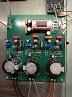
I've been using Pico York for a few days with my AD1865 DAC
Everything works great!
A few comments:
The additional PCB for the u-FL is a great idea
It would be good to think about an external power supplyUSB power supply from a computer is not state of the art
Other than that - great device
Thank you and I highly recommend it!
Everything works great!
A few comments:
The additional PCB for the u-FL is a great idea
It would be good to think about an external power supplyUSB power supply from a computer is not state of the art
Other than that - great device
Thank you and I highly recommend it!
Attachments
I can do it with 1024fs clocks 24bit 48kHz max, or 16 bit 96kHz.Hi, TDM 16 channels outputs possible with this hardware? Very interested ☺️
Perhaps 2xTDM8 is also an option. Please PM me more details of what is needed.
Yes, indeed. but I guess it is just simpler to get everything as one package.There is a small PCB for header to u.fl in the Miro 1862 thread.
Ok, So as I understand it this transport can work as master or slave? And, if It can do DSD512 natively win 10-11 wih 1024 clock? Possible to get one special made with one of those better clocks? And special firmware-drivers that then could handle DSD512? 4channel? Would be awesome!!!Thank you!
In theory it can output up to 4 DSD streams, up to DSD512 with 1024fs clock (by default modules are equipped with 512fs. These can be replace or you can also feed external clock). So far the module only tested on stereo DoP, DSD256.
Since I've already got couple of requests for Native DSD, I may consider updates of the firmware for DSD support in the future.
At the moment there are couple of other items that I need to implement ASAP 🙂
If anyone would like to volunteer for DSD firmware tests, please PM me. I'll send the module for free in exchange for conducting tests of the firmware, collecting debug information etc.
Hi, your interface looks really nice - I like that it has provisions for input as well as output.
One of the configurations I noticed wasn't under tested was non-TDM I2S output, I2S Input at the same time. Would this be a setup that could function?
For example. PCM1808 2ch input, 2x PCM5102 output for 4ch.
Would the lack of onboard clocks on the "mini" version make this kind of setup more challenging, or would the MCU PLL clock be sufficient? (functionally).
Thank you!
Hello,
I think it is possible to do, there is still one pin (F2) available to output one more I2S data line:

Indeed, currently there is no such option, I only have 2 ch in + 2 ch out and 4ch output separatly.One of the configurations I noticed wasn't under tested was non-TDM I2S output, I2S Input at the same time. Would this be a setup that could function?
For example. PCM1808 2ch input, 2x PCM5102 output for 4ch.
I think it is possible to do, there is still one pin (F2) available to output one more I2S data line:
No, there will be no difference. Mini version has different (and a bit more convinient) pinout and can be functional without external clocks with the PLL.Would the lack of onboard clocks on the "mini" version make this kind of setup more challenging, or would the MCU PLL clock be sufficient? (functionally).
Around what time do you anticipate the 'mini' design to be ready? I think this would be one of the most suitable solutions for the setup I'm currently rebuilding.
The hardware part is good, I do not expect any changes. I'd say the firmware is also available as beta version as not all of the modes were tested properly. (The difference in firmware between 'pico' and 'nano' versions is only in MCU pin assignments.) 2ch i2s out and 2ch NOS output tested well at the moment.Around what time do you anticipate the 'mini' design to be ready? I think this would be one of the most suitable solutions for the setup I'm currently rebuilding.
- Home
- Vendor's Bazaar
- USB UAC2+HID Multichannel input/output interface York