Thank you, some interesting info. Did you also tested circuit with square wave or just frequency response?
this is without the 50kc pole 1kc blok 6ns rise time ,above with the 50kc pole

Still a little bit unclear if I disconnect 1.4k resistor from 3n3 capacitor, capacitor also will be disconnected from circuit. How then 2122Hz (75uS) pole will be formed?If you want to test the circuit without the high-frequency pole, you should test with the 1.4k resistor disconnected from the 3n3 capacitor, rather than shorting the resistor.
Alex
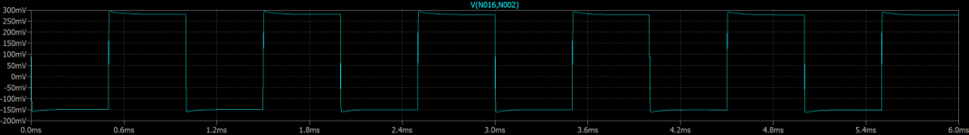
Hello Mr.Sarunas.A square wave test failed. Some pictures you can see here:
https://www.diyaudio.com/community/threads/vacuum-state-rtp3c.151733/page-46
I got the same results with LTSpice simulation and with practical circuit. Unfortunately nobody commented this fact 🙁 There is a lot of builders of FVP5 but strange that nobody tested it.
First of all thank you for sharing the LTspice simulations, it has helped me a lot, since I don't have the knowledge of the program like you.
That said, in order to see the square wave through LTspice simulation or the oscilloscope, you need a reference probe, which is taken at the output of the generator and the other probe is the one that measures at the output of the phono preamplifier.
I attach a screenshot from LTspice.
I hope this helps you and how not to expose your results.
Regards.
Attachments
Dear Mr Rasmussen, I'm delighted to see that Allen Wright continued to improve his FVP design. I received (eventually) his TPCB, and the FVP has given me some good ideas on how to build my own customized preamp. I'm particularly grateful for this update and possible improvement of the SuperReg, and the warning about the non-linear gate capacitance of the constant-voltage mosfet employed in the SLCF. I have had to forego the SLCF, as I wanted the line stage to drive headphones in stand-alone mode. As I'm still in design mode, all your suggestions are particularly valuable. Thanks also for your personal photos of your time with Allen.I have another project in mind that requires +100V and I changed values for +250V and it looks like below.
NOT YET BUILT - SUGGESTED ONLY:
View attachment 1262780
A couple of explanations. The LM317L sets up 1mA and all the current goes through that LM431. This is better than using a resistor. It means that the added 1mA to the end result is also current sourced. The TIP32C redirects the current, the (red?) LED does mean that it is limited to 20mA in the shunt, but without the LED it can sink quite high currents, use appropriate heatsinks. The *47R needs to be adjust as per current required. Allow up to 30mA for the circuit and 20mA in the shunt.
View attachment 1262783
I used 22K here instead of LM317L, but on the surface it does seem it might work. The 0.1uF I would use X2 class polypropylene. No values above are set in cement.
Any suggestions and critique is welcome.
.