[FONT=함초롬바탕]Report on [/FONT][FONT=함초롬바탕]Jaehong's Linear Power Supply Kit from Manfred (Germany) :[/FONT]
[FONT=함초롬바탕]I ordered the Linear PS as a Kit from Jeahong from Korea. I paid 152 Euros for the Kit incl. shipping and pay-pall cost.[/FONT]
[FONT=함초롬바탕]Custom clearance and VAT in Germany did cost me an other 26 Euros. So in total it was 178,-Euros.[/FONT]
[FONT=함초롬바탕]1. The Kit and Assembly:[/FONT]
[FONT=함초롬바탕]The transaction was fast and I received a package which included:[/FONT]
[FONT=함초롬바탕]1 huge, high quality Transformer 220V, with 2 secondary leads for 6V and 1 secondary lead for +/- 16V.[/FONT]
[FONT=함초롬바탕]1 high quality PCB with good printings for all components.[/FONT]
[FONT=함초롬바탕]1 pack with all required parts, as caps, rectifiers, etc incl. mounting bolts and nuts.[/FONT]
[FONT=함초롬바탕]I had received by mail upfront some pictures and guideline for the assembly. Together with the printing on the PCB it was easy to assemble the kit.[/FONT]
[FONT=함초롬바탕]It took me approx. 2 hours to solder and mount all parts. I used Wondersolder and it was very easy to get good soldering joints.[/FONT]
[FONT=함초롬바탕]I spend most time to make the caps "naked" and mark them all. If this sounds better, I do not know, but I do this on all my audio kits.[/FONT]
[FONT=함초롬바탕]I tested the kit and the yellow LED came on, so this should be the basic check, that everything is done correct.[/FONT]
[FONT=함초롬바탕]BTW, I should mention, that I do not connect the +/-15 Volt for the analog output, since I do not use them in the Oppo 93.[/FONT]
[FONT=함초롬바탕]The mounting of the assembled LPS into the Oppo is not a big issue neither, it took me about an other half an hour to swob the power PCB.[/FONT]
[FONT=함초롬바탕]In Germany we get the Oppo already supplied with a 3 prong power socket and earth/grounding connection is already done to the chassis.[/FONT]
[FONT=함초롬바탕]However, I changed the power socket as well, since I got a 3 prong power inlet socket supplied with the kit from Jeahong. [/FONT]
[FONT=함초롬바탕]So I could leave all removed parts in original status to re-assemble it back to original if wanted.[/FONT]
[FONT=함초롬바탕]Comments:[/FONT]
[FONT=함초롬바탕]The Linear Power supply is a non sophisticated, non high-end basic power supply with caps from a korean supplier (non high-end at least to my knowledge).[/FONT]
[FONT=함초롬바탕]Therefor I was skeptical about the performance and was hesitating, if I should not replace the caps and rectifiers with better parts, such as Blackgate or Elma caps.[/FONT]
[FONT=함초롬바탕]However, then I decided to build it just as Jeahong supplied it and give it a try.[/FONT]
[FONT=함초롬바탕]The 2 separate 5V DC for the digital part to the Oppo are filtered/buffered each with 3 x 10.000uF/16V caps, this is really huge, isn't it?[/FONT]
[FONT=함초롬바탕]2. Video and Audio performance:[/FONT]
[FONT=함초롬바탕]Jeahong recommended to give the PS some hours of burn-in to settle the caps, which I did with a 4 days x 24hours continuous bluray operation in repeat modus.[/FONT]
[FONT=함초롬바탕]Video: [/FONT]
[FONT=함초롬바탕](my components to validate are: JVC DLA X7 on 3 mtr wide screen, connected with Wireworld Ultraviolett 6 HDMI cable).[/FONT]
[FONT=함초롬바탕]Picture quality improved, it seems to have more color and contrast, which probably is the result of less noise on the power supply.[/FONT]
[FONT=함초롬바탕]The look is just more 3 dimensional, I think this is the best way to describe it. (I have not tested it with 3-D bluray).[/FONT]
[FONT=함초롬바탕]Audio: [/FONT]
[FONT=함초롬바탕](I connect with a Wireworld Starlight 6 HDMI cable to an Anthem MRX700 (preamp only) which is feeding an Anthem P5 multichannel amp to a modded Klipsch 7.1 LS-System)[/FONT]
[FONT=함초롬바탕]High frequency distortion is reduced, much less fatiguing now and lot easier to your ears.[/FONT]
[FONT=함초롬바탕]Voice easier to understand.[/FONT]
[FONT=함초롬바탕]Speakers are now disappearing better and sound space is more in the room.[/FONT]
[FONT=함초롬바탕]At the beginning, I thought that bass has lost weight, but it is just less boomy and more precise.[/FONT]
[FONT=함초롬바탕]I can turn up level now by 3 to 5 dB and still thinking it is lower volume then before the upgrade.[/FONT]
[FONT=함초롬바탕]This is a clear indication, how much less stress is put on your ears with the LPS.[/FONT]
[FONT=함초롬바탕]3. Summary:[/FONT]
[FONT=함초롬바탕]The Kit is a no brainer for everybody who wants a cost effective upgrade for his Oppo 93.[/FONT]
[FONT=함초롬바탕]It is easy to install (and to assemble if you can hold a solder iron).[/FONT]
[FONT=함초롬바탕]The performance improvement is surprisingly big, especially when you compare it with the cost of "professional modders".[/FONT]
[FONT=함초롬바탕]After the LPS in the Oppo 93, it is very difficult to listen to any SMPS equipped blu-ray player anymore, its just pain on your ears.[/FONT]
[FONT=함초롬바탕]Jeahong, please fell free to use my report as reference to other possible customers or on the forum.[/FONT]
[FONT=함초롬바탕]Thanks.[/FONT]
MfG / Best regards ..... Manfred Weil ...... emw.weil@t-online.de
interesting, as the video and audio is all digital data to the outside world, any scope shots to show what may be happening to the digital data to create such an improvement between an SMPS and a linear supply?
It is one of the major inconveniences/disasters (sorry if anyone finds the use of this word inappropriate) of the internet that legitimate sites, such as Jae Hong Lee's blog, become infected by malicious, devious, criminal, bastards.
Going to his blog brings up ..........
Reported Attack Page!
This web page at blog.paran.com has been reported as an attack page and has been blocked based on your security preferences.
Attack pages try to install programs that steal private information, use your computer to attack others, or damage your system.Some attack pages intentionally distribute harmful software, but many are compromised without the knowledge or permission of their owners >>>>>>>>>>>
Diagnostic page for blog.paran.com
What is the current listing status for blog.paran.com?
Site is listed as suspicious - visiting this website may harm your computer.
Part of this site was listed for suspicious activity 7 time(s) over the past 90 days.
What happened when Google visited this site?
Of the 2548 pages we tested on the site over the past 90 days, 16 page(s) resulted in malicious software being downloaded and installed without user consent. The last time Google visited this site was on 2012-07-28, and the last time suspicious content was found on this site was on 2012-07-28.
Malicious software includes 23 trojan(s), 10 exploit(s), 3 scripting exploit(s). Successful infection resulted in an average of 17 new process(es) on the target machine.
Malicious software is hosted on 5 domain(s), including junggomania.nefficient.co.kr/, securitynews.co.kr/, 175.115.53.0/.
3 domain(s) appear to be functioning as intermediaries for distributing malware to visitors of this site, including blog.paran.com/blog/, blog.paran.com/common/, 175.115.53.0/.
This site was hosted on 1 network(s) including AS4766 (Korea Telecom).
Has this site acted as an intermediary resulting in further distribution of malware?
Over the past 90 days, blog.paran.com appeared to function as an intermediary for the infection of 13 site(s) including daum.net/, blog.paran.com/zm6ueigs/, blog.paran.com/ihs7100/.
Has this site hosted malware?
No, this site has not hosted malicious software over the past 90 days.
How did this happen?
In some cases, third parties can add malicious code to legitimate sites, which would cause us to show the warning message.
Next steps:
Return to the previous page.
If you are the owner of this website, you can request a review of your site using Google Webmaster Tools. More information about the review process is available in Google's Webmaster Help Centre.
interesting, as the video and audio is all digital data to the outside world, any scope shots to show what may be happening to the digital data to create such an improvement between an SMPS and a linear supply?
You maybe forget that digital datas are converted in analogue in one or another stage of the machine... High or low frequency noises introduced by a noisy/switching PSU may interfere with the digital processing, increasing the need for error corrections in the system, and degrade at last the information to be analogue converted at the end...
It is a very solid fact that a linear, a more quiet PSU increase much the quality of the sound (and video) in a both digital or analogue audio systems/devices.
One do not necessary need an oscilloscope to hear the difference of a improved sound (or see a better quality picture on the screen)... but may need more knowledge to understand well the processes....
Last edited:
I`ve been visited before the Jae Hong Lee's blog site without any problem or infection... But now I can see (confirm) too that his blog site is blocked by Google.
Jae Hong Lee will may find necessary to move his blog on another host site... or just continue his participation to this forum site. 🙂
Jae Hong Lee will may find necessary to move his blog on another host site... or just continue his participation to this forum site. 🙂
Yes but a lot of digital noise is created by the digital switching itself, in fact most of the noise is created by fast rise time (most digital devices these days have very fast rise times) switching of digital devices. From my experience the only way is to isolate your final DAC stage and have the minimum of digital devices (ie the DAC only) in that isolated stage, that is the ONLY way to isolate yourself as much as possible from any digital noise on the supplies and the return (ground). And no a linear of SMPS if designed properly for the system will have no effect on the digital signals, the power supply is last in the chain of any high speed switching system (digital video is a good example), the on chip and interplane capacitances provide the inital charge, with the small MCLL capacitors providing the next and so on through reservoir caps back to the PSU (linear or SMPS). If you realy want to improve any digital signal integrity you are better concentrating on the PCB structure (all signals stripline with adjacent contigous planes for optimal return current paths, close coupled power and ground planes, 0.1mm dielctric)
and proper decoupling of the power supplies, an art not often practiced, instead rules of thumb.
No I do not agrere that SMPS are always inferior to linear, they are not and are not the main source of noise that a digital system creates, they do contribute as dose all switching digital devices.
and proper decoupling of the power supplies, an art not often practiced, instead rules of thumb.
No I do not agrere that SMPS are always inferior to linear, they are not and are not the main source of noise that a digital system creates, they do contribute as dose all switching digital devices.
I imagine the temperature inside the player is now higher due to the linear regulators (the Oppo 93 already runs quite warm). Have you done any testing in this regard?
It is quite hot. but heatsink of my LPM is attached to bottom plate and dissipates heats efficiently. It becomes global warming.
see the photo od my LPM in my blog. then you will understand it.
see the photo od my LPM in my blog. then you will understand it.
I have made Linear power module for OPPO 95 .
Those who want to be beta tester . give me e- nmail to pcaudio@paran.com or PM
my blog to http://pcaudio.tistory.com
I found out that OPPo 95 analog sound is really superb. much better than coaxial out sound.
More spacious , more clean, detail .
With OPPO 95 LPM, the video became quite aatractive with much reduced noise.
I am very inmpressed with OPPO 95
I am preparing for mass production to meet the demand of OPPO 95 users .
Last edited:
1.Remove various distortion producing parts on the AC input.
2. Damp various parts on the switching supply.
3. Remove the toslink connector....it is an LED and they mess up the sound.
4. Seriously damp the disc cover and mounting pads of the transport with constrained layer damping material.
5. Seriously damp the disc spinner with a piece of constrained layer damping material....very important.
6. Black the underside of the disc cover and all around the laser mechanism using flat black paint.
7. Ground the disc cover.
8. Change the main diodes in the switching supply to damped soft recovery types.
9. Twist the wires going to and from the toroidal transformer.
10. Mount the toroidal power transformer off the chassis on a piece of quarter inch thick wood.
11. Change the rectifying diodes on the analog power supply board to damped soft recovery types.
12. Damp the ringing in the transformer as the diodes shut off with a circuit that includes a nude Vishay resistor.
13. Change the preregulator for the DAC digital supplies to a modified Dexa regulator and mount it on a much larger heatsink.
14. Change the regulator on the analog power supply to the ESS DAC to a fully discrete cascoded current sourced shunt regulator.
15. Change the stock 54 meg clock for the ESS DACS to a super low jitter 100 meg clock powered by its own discrete cascoded current
The above modifications and upgrades for Oppo 095 were suggested by an upgrade company named EVS.
I have implemented the modification listed above with numbers 2,4,5,6,7,9,10,11 and 12 being easy to be carried by me.
Additionally, I put ferrite rings in all the internal connecting cables, power supply cables as well as in the internal ac main cables.
I have also put aluminiun foil tapes in the inner sight of the upper cover of the player as well as on the outside bottom base for shielding and dabbing.
I also changed the MKT x2 capacitors in the main’s filter to the Wimas x2 MKP.
The above modifications lead my oppo 095 to behave much - much better than before in the audio as well as in the video section.
In the analogue power supply I changed the uf4007s diodes to the much faster BYW29s (25ns instead of 75ns) and I bypassed them with 22n polystyrene capacitors.
I have also ordered some Elna silmic ii 220mf 16V capacitors to replace the existing TA low esr capacitors in the audio board.
Waiting for my Elnas, I have decided to try bypassing the existing 220mf capacitors in the stereo board with tantalum 47mf 35v.
Doing the above mod, I was expecting from previous experience, that the upper frequencies will become more “sweet and tasty” with lots of details, clearer more enjoyable and adictable .As long you can hear them nothing please you anymore in these areas.
And that was the case.
Unfortunately the other part of the frequencies are not affected, in a way that, the balance of the system changed in favor of the upper frequencies. The meds and tweets seem to be louder.
I am now planning to remove the 47mf tantalums and replace them with 4.7 mf to lessen, let’s say the effect of the tantalums and keep the balance.
During the above process, I measured the power supply voltage after the byw29s and found out that it is +24.45dc and -24.85dc and after the main regulators, the voltage that feeds the final op amps is measured and found out that it is +15.5 and -15.1.
I wonder what the reason for this problem is and whether this affects and decreases the sound of the op- amps.
If this is caused by the mismatching of the diodes, there is another question to be answered. Do the diodes need matching?
Can anybody please give me an idea? Thanks
I can say that in your above list of modifications there are some which have impact in sound/video quality, and some not at all.
Most quality increasing in both video/audio come from increasing filter capacities in the switching PSU, changing the main oscillator (for main processor) with an less jitter one, and dedicate a own 3,3v low noise regulator for it. This is very important for the video first and audio second.
On audio/DAC stage of the player is the same clock oscillator which is the key part for increasing the quality of the sound. This clock is to be at minimum 100Mhz, mounted right beside to the ESS9018 chip, and feed it with its own very low noise regulator. The another ESS9018 DAC for multichannel have to have its own clock, else the player will not boot. The original 54Mhz clock is used for both ESS DACs. One have to chose which of those two DACs is to be used most, and modify the clock for it accordingly. Is here only about to cut the clock trace for that one which will get a better oscillator.
I will suggest using 112,896Mhz oscillator if one play most CDs. Superior sound quality come from using an 122,8 Mhz clock too.
The most important for audio stage is to use a better analogue PSU than that low quality one Oppo has installed in their player.
At last, are quite many others small modifications on the audio board which can increase the sound quality quite much. I refer her to I/V and final opamp amplifier stages.
In your case, about the +/-15v regulators, the difference between the two tensions values come from the regulators its self. Their are not matched for the same tension value. This is quite difficult to find two identical regulators, and they become different anyway when it get hot... So, the solution is to make one of those variable (by mounting a potmeter on one of it). In this way one can get the equal values of the final tensions for the 15v rail. Here is important to have very equal values (best identical, and this after the system become temperature stable).
I personally think that is a bad idea to use an transformer (in this case Rotel) which give 24v unregulated, for make they 15v regulated of it. The regulators generate in this way only unnecessary heat inside the player... I`ve just removed that famous Rotel transformer and used an Rcore one which give me 18v unregulated for the same +/-15v regulated...
Mounting extra and local regulators for the I/V - final stages will also increase much the sound quality and the general dynamic. At last, using another opamps for those stages is very important for the final result. But the existing ones are good enough anyway.
I will suggest you to mount much higher value for those 220µF/16v caps, and yes, tantalum is very good choice. 47µF in your case is not a good choice... Mounting many paralleled caps will decrease much the total ESR of the resulting capacity (but will increase the coast of the modification...)
By the way, the rectifier diodes in the system are far from important for the final result of the modifications. One may forget this aspect and let they as it is...
Mounting ferrite rings everywhere on the power wires is not very fortunate. The result can be opposite to expected... One have to chose carefully where those rings is to be mounted. Some time, due the high currents which goes through the wires, it can create in conjunction with those ferrite rings, big enough spikes which can disturb the further systems coupled to that wires...
Last edited:
Thanks Coris for your advice and sugestions.I apretiate your promt and detailet reply!
I agree with you that by increasing the filter capacities in the switching PSU can possitivly effect the performance.Actually I have done that allready.I Have changed the 120mf with one of the older series of Nichicom 180mf 450v paralled with an external and mounted next to the rotel Transforer, 60mf mkp running capacitor totalling 240mf.
Do you thing that by furher increacing the capacitance I will get better results?
Changing the clock is a quite difficalt dask for me.Maybe I will ask from a profetional to do it .Even if I doudt whether I will find one here in Cyprus.
A better analogue PSU for audio stage is among my capabilities and I will try it .I am thinging o using some special vertion of Salas srpcu.Any other sugestion?
Using another opamps for Iv and final stages is something that I am thinging to do.
Everybody speaks about op627s with a broun dog.What do you thing?
Alternatively ,what about biasing the existing op amps to run in Class A mode with a smalll resistor.
Cost is a no object for Paralling more tantalums .But what is the total capacitance you sugest?
Regarding the rectifier diodes in the analogue power suply I have to say that,It was the very first mod that I did, after about a week of carefull lisenig and Judging of Oppo.
So by chainging the diodes to byw29, the resuld was a smoother sound in all ereas, but especialy on the high frequiensicies that Iand more enjoybale sound.
I think is a little misunderstanding about the switching PSU capacitors. It were my fault to not be more precise... Increasing the filtering capacity in this PSU is about the final capacitors on the low voltage outputs. The main high voltage capacitor may be in place as it is... If this capacity is modified, it may change the parameters of the entire PSU, and specially, if long wires are involved in this high voltage stage of the switching PSU is not very fortunate... I should not touch this one cap.
I know that changed out the oscillator is not an easy task, and it have to be done very carefully.
One can improve the existing analogue PSU, so is not necessary to change that completely out. I personally had big problems with that original serial PSU (the caps got hot, high ripple current, and so...) so I decided to build a completely new one from scratch. Maybe it was only in may case this problem... So, one may take a closer look on that in the specific case.
Changing the opamps involved in I/V and final stages may not bring the best result at once. I experimental a lot with this, and I can say that it is not a very easy task too. Is quite difficult to work/experiment with that big analogue PCB, specially when that is mounted in place up side down, and removing components from that board can easy destroy the traces... I will suggest (for a not very well experienced modder) to be used those original opamps. They are a good quality/parameter ones. I think that may be easier to experiment first with another final opamp if you really want, and then try with the I/Vs... When is to change out the original opamps, one may take in to consideration too that have to be changed accordingly the resistors around, as the parameters of new opamp can be different... So as a conclusion, is not quite easy...
For filtering/decoupling caps in those opamp stages I will suggest few hundreds µF, maybe 1000 of such paralleled tantalum caps. They are quite small at low voltage rating...
Maybe I will try myself this about rectifier diodes in the PSUs one day...
Last edited:
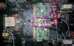
Here is how it looks my (maybe...) finish mod of the stereo stage of BDP95. It do not look very nice, but it works very nice...
I will say that about the mods of this player, one have to look for (hear for...) not only good enough high frequencies of the sound, or a well defined bass, and so on. Here (using a such advanced DAC chip) one have to look for obtain a well defined (3D) sound stage. When everything (or almost all...) are in right place in this mods, it is possible to hear the instruments where they are in the stage at the original recording. Specially in the back and forward planes. One do not have to feel the sound coming directly from the speakers. The sound have to be in the whole listening room, and the spekers become in this case transparent.
I was quite surprised to find out that the informations about locations of the sounds in the sound stage it come even from poor processed files as mp3 encoded with 128kbs. After a quite simple processing and up sampling, it was possible to get a very good sound stage out of such played files...
In one of my experiments I obtained at last a very fine/defined sound comming out from this player. But every of the instruments sounds was placed in the same plane, between the two speakers. That was not good at all... When were possible to hear the instruments back and forward the speaker line, that were the right result...
I have to say that this is very difficult to be achived. Not all the performants opamps or components can bring a such result. But details about what is right in this respect, I think I will may keep for my self...
Attachments
Last edited:
I suggest you yo try Schottkey diode as Ayre DX-5 does.
It is much better than fast recovery diodes.
And any one in here want to try linear power module rather than switching power unit in OPPO 93 /95 , please send PM. I can send Linear power Module PCB or PCB with trodidal transformer. I guess there are many who can do solsering .
It is much better than fast recovery diodes.
And any one in here want to try linear power module rather than switching power unit in OPPO 93 /95 , please send PM. I can send Linear power Module PCB or PCB with trodidal transformer. I guess there are many who can do solsering .
Upgrading & moding oppo 095
Below 100V Schottky is likely to perform better due to the absence of reverse recovery and due to the fact that higher capacitance does not matter that much at low voltages.
Between 100V and 200V ultrafast diodes perform quite good and their reverse recovery charge is not that high. There are Schottky diodes rated for more than 100V but in most cases they exhibit similar or higher forward voltage drop than ultrafast ones (threshold voltage is still lower, but internal resistance is higher). There are some exceptionally good performers like MBR40250, though.
Above 250V there are no suitable Schottky diodes but there is a relatively new (and expensive) type called SiC diode that does not exhibit reverse recovery either. It has its own drawbacks, though, like not very good surge capability, high forward voltage and positive temperature coefficient. This is not yet a mature technology. Check SDT12S60 (first generation from Infineon), IDT16S60C (second generation) and CSD20060D from CREE.
For 600V there are special Hyperfast diodes, like 15ETX06 or APT16DQ60K, that feature considerably lower Qrr than Ultrafast ones at the expense of higher forward voltage drop. These are intended for hard switching.
Taken from the thread Fast vs Schottky
Dear Lee, assuming the above are correct, what schottky diode you suggest for Oppo 095 analogue power supply?
Also what about the bypassing capacitors, are they still needed?
Regarding the linear power module to replace the switching power unit in OPPO 95, I might be interested, but can you give me an idea as to how it looks, how much it costs etc.
Aditionally if I am correct the APT16DQ60K is used by Oppo in the switching power unit
Dear Coris! The resulting photo of your player definitely looks cool but also frightening to those of us who are not so experience as you are.
I have read your posts on 9 and 14.11.2011 about large decupling capacity with Tantalum and I will try it, as long as from my experience, despide many others in the diy forums , I very much appreciate the Tantalum Caps and their effect in audio as decupling caps.
From the commercial point of view Naim audio, a historical and reputable hi end company still use them.
I believe that, big capacitance will also boost the bass section in my case and somehow the balance in the audio spectrum will be restored .
The local regulation is an option and will be considered as well but, the problem is that the double cited pcp of the audio board and the smd parts , does not help at all the moder and create a degree of difficulty.
I will come back with photos after the vacations.
There is another thing that worries me. This large capacitance is somehow at the output of the regulators Lm317/lm337.Acording to another threat in this forum, the capacitance at the output of the said regulators should not exceed the 560mf otherwise the regulators create noise. What do you thing.
Anyway I will experiment with both and I will post the result.
Hi Andy
I can agree that those mods as I`ve done it are not quite easy tasks. Anyway, one can try to do what one can... Here is more about informations, than "how to do it"...
The only problem with large capacities at the regulators output is the power start up sequence, when the capacitors take large currents. But the most of those regulators have an internal protection against over current. This protection will fix the start up problems... Of course, one may read the data sheet of that regulator to ensure that oscillations or other thing will not occur when large capacities are on the regulators output. So far I did not have difficulties to put in place those large capacities.
Is quite important when place such decoupling capacities to avoid (long) connection wires. That because SMD caps are better....
Hi! Andy
Thanks for your nice comment.
You can see the OPPO 93 and OPPO 95 Linear power in my blog at Jae H. Lee Blog :: TVIX 6620 ? OPPO 93 ???? ??? under home theater section
I have extra PCB and troidal transfomers to those who want to build by themselves.
The kit which as all parts is 150 USD, the fully assembled and soldered one is 239 USD.

OPPO 95 LPM module

OPPO 93 LPM module


Thanks for your nice comment.
You can see the OPPO 93 and OPPO 95 Linear power in my blog at Jae H. Lee Blog :: TVIX 6620 ? OPPO 93 ???? ??? under home theater section
I have extra PCB and troidal transfomers to those who want to build by themselves.
The kit which as all parts is 150 USD, the fully assembled and soldered one is 239 USD.
OPPO 95 LPM module
OPPO 93 LPM module
Last edited:
- Home
- Source & Line
- Digital Source
- Upgrading & modding new Oppos, BDP-93 & BDP-95