Also my thoughts, but wasn't shure: I assumed either there is something very sophisticated which I don't know or simply nonsense.I do not believe that connecting them together in parallel (MOSFET and BJT), and placing them in a circuit (as shown) -> is possible... at all.... ...wouldn't work correctly without changing the way MOSFETs / BJTs are driven....
Reduction of resistance. The device contributes to the output impedance.
Hmmm... now what?The TIPC isn't connected to the output line (there's no blob).
C12 also sets the low freq corner. If you increase it a lot, you'll get a lower LF corner which may cause very low frequency movement of the speaker and possibly LF oscillations aka motorboating.Hi All,
Just wondering, Would be any benefit in using higher value capacitors in an amplifier's driver stage? currently there are 220uF in the circuit, would be any benefit in replacing it with , let's say 1000uF capacitors?
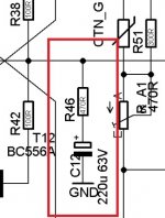
I'm referring to the marked capacitors in the attached schematic.
Thanks
It would be smart not to tamper with it too much.
Jan

Thank you for mentioning it.C12 also sets the low freq corner. If you increase it a lot, you'll get a lower LF corner which may cause very low frequency movement of the speaker and possibly LF oscillations aka motorboating.
It would be smart not to tamper with it too much.
Jan
Isn't the amplifier's LF corner 1.54Hz? please correct me if I'm wrong.
jan.didden said: It would be smart not to tamper with it too much.
In amplifier simulations (LTspice) I noticed the following:
The feedback DC blocking capacitor adds distortion in the lower frequencies, e.g. below 500Hz, depending on the capacitance and the current flowing through it. Rising it's capacitance lowers the distortion, respectively shifts it further down. Increasing the value of the resistor in series with the DC blocking cap also lowers the low frequency distortion; of course in this case one has to tweak also the feedback resistor to reach the equal gain.
How big do you think this capacitor can be? I've seen circuits with e.g. 1000µF or more for it.
In the "TO39AMP" I'm working on now I'm using 470µF.
Last edited:
Could c10 be swapped for 1 uF only but mkp radial ? More damped sound and improved subjective transcient...worth to try ?
0.1 uF across the 220 uF of the zener for improving the filtering ?
Also what is the c10 brand and model (leads spacing)
0.1 uF across the 220 uF of the zener for improving the filtering ?
Also what is the c10 brand and model (leads spacing)
Of course. You're modifying the feedback level and that translates in changes in distortion profile. It's not as if 'the cap adds distortion'.In amplifier simulations (LTspice) I noticed the following:
The feedback DC blocking capacitor adds distortion in the lower frequencies, e.g. below 500Hz, depending on the capacitance and the current flowing through it. Rising it's capacitance lowers the distortion, respectively shifts it further down. Increasing the value of the resistor in series with the DC blocking cap also lowers the low frequency distortion; of course in this case one has to tweak also the feedback resistor to reach the equal gain.
How big do you think this capacitor can be? I've seen circuits with e.g. 1000µF or more for it.
In the "TO39AMP" I'm working on now I'm using 470µF.
The way to calculate is first decide on the lower cutoff in your freq response, then calculate the cap value for that Fc against the resistor in series with it.
Jan
Yes, from the top of my head seems in the right ballpark.Thank you for mentioning it.
Isn't the amplifier's LF corner 1.54Hz? please correct me if I'm wrong.
Jan
Way back, I saw this apparently done in a mod on an ebay offering and asked about it but didn't even get any speculation:I do not believe that connecting them together in parallel (MOSFET and BJT), and placing them in a circuit (as shown) -> is possible... at all.
https://www.diyaudio.com/community/threads/some-questions-on-an-adcom-5400.254229/#post-4085948
Just want to add: this is already excessive, any rumble or LF junk will gobble up power and may damage the woofers. No idea who decides these nonsense cap values.Thank you for mentioning it.
Isn't the amplifier's LF corner 1.54Hz? please correct me if I'm wrong.
22uF for a 15Hz lower 3dB point is much more sensible.
The mind shudders with talk of an upgrade to 1000uF ...
See attached graph with 22uF showing a -3dB point of about 15Hz. (Assuming series R of 22k, hard to read on the pic).
Jan
Attachments

Last edited:
Just want to add: this is already excessive, any rumble or LF junk will gobble up power and may damage the woofers. No idea who decides these nonsense cap values.
22uF for a 15Hz lower 3dB point is much more sensible.
The mind shudders with talk of an upgrade to 1000uF ...
Never thought about photo rumble affecting an amp like that.
I had flapping woofers and a power amp repeatedly shut-down because it was "DC coupled" and did not like my phono source.Never thought about photo rumble affecting an amp like that.
OTOH, Doug Self and others preach over-size electrolytics to avoid distortion. (The take-away is a few film-caps to define a sane bass roll-off and any e-caps much larger.)
What I find interesting is that often people ask to oversize caps in the expectation it sounds better, but never someone suggests to change all resistors in an amp to 1MegOhm because bigger is better. 😎
Jan
Jan
Thanks for the explanation.Just want to add: this is already excessive, any rumble or LF junk will gobble up power and may damage the woofers. No idea who decides these nonsense cap values.
22uF for a 15Hz lower 3dB point is much more sensible.
The mind shudders with talk of an upgrade to 1000uF ...
See attached graph with 22uF showing a -3dB point of about 15Hz. (Assuming series R of 22k, hard to read on the pic).
Jan
R46 is connected in series to C12, it's value is 470 ohm.
Attachments
I was referring to the FB series R, they are often in the range of 22k, but I can't read it.
That determines the mid-band gain together with R46, as shown in the sim circuit I posted.
Jan
That determines the mid-band gain together with R46, as shown in the sim circuit I posted.
Jan
Are you reffering to the marked one?I was referring to the FB series R, they are often in the range of 22k, but I can't read it.
That determines the mid-band gain together with R46, as shown in the sim circuit I posted.
Jan
Attachments
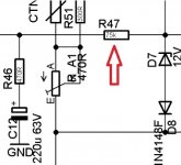
Just confirming🙂Of course, is there another feedback series R somewhere?
Jan
Well, it's 75K ohm.
- Home
- Amplifiers
- Solid State
- "Upgrading" Amp drivers capacitors