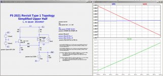
Isn't this just standard F5 without your extra current sense resistors ?
I thought you want to remove Rs ?
PS We have different interest. I am more interested in distortion.
Patrick
I thought you want to remove Rs ?
PS We have different interest. I am more interested in distortion.
Patrick
dunno how's that with you guys, but I have a problem with F5
pretty much I have zillion of iterations of same, even few with just one pot needed for fire up-set-go ( and yes, confirmed as functional on T-Bed) , with everything solved in DC domain, but my problem with F5 is that I'm unable to sort main obstacle - I can't solve AC behavior of F5 to have at least half expectable performance, without using THD Spectra measurement
in short - change input JFet source resistance, or change JFet for another one from same bag, THD SPectra goes ........ somewhere
in short, I can't solve it to be simple enough for regular Greedy Boy
though, it needs to be qualification ticket for membership in Papaland, having decent soundcard, proper attenuator/interface for same and decent dummy load

1W 1kHz into 8R. H2 0.0006%, H3 0.001%.
Wasn't even my own. No distortion trimming either.
What is the problem ?
F5X -- the EUVL Approach - The Build Thread
Cheers,
Patrick
Wasn't even my own. No distortion trimming either.
What is the problem ?
F5X -- the EUVL Approach - The Build Thread
Cheers,
Patrick
Isn't this just standard F5 without your extra current sense resistors ?
I thought you want to remove Rs ?
PS We have different interest. I am more interested in distortion.
Patrick
Yes, it was accidental that I had the source resistor in that example. Here is a similar simulation with both the source resistor gone AND the Q3 drain resistor gone. Wacko circuit self regulates no matter what. But, the idle current sensitivity to small parameter changes gets bad as those resistors get smaller.
Attachments
1W 1kHz into 8R. H2 0.0006%, H3 0.001%.
Wasn't even my own. No distortion trimming either.
What is the problem ?
F5X -- the EUVL Approach - The Build Thread
Cheers,
Patrick
X is different beast
well, it isn't about building for my self ....... I certainly don't need more amps and if I'm ever building any just to have, it'll be certainly one involving greater emotional and intellectual challenge, than any already solved to last bit
Member
Joined 2009
Paid Member
The larger the value of R1, the more stable the bias.
I used 1.2R.
Patrick
1.2R is large in series with an output driver and a speaker load. Feedback will keep the output correct, but significant voltage headroom will be lost. Consider a 4R load with 1.2R in series. The speaker will only receive a maximum of 77% (4R/(5.2R) the possible voltage swing as with R1 removed.
As far as the amp is concerned, the effective load is (R9//R10) + RL.
If RL is 8R, then it is less than 10%.
I would be happy to have 0.6R more Zout and 6dB less H2.
Patrick
If RL is 8R, then it is less than 10%.
I would be happy to have 0.6R more Zout and 6dB less H2.
Patrick
You are correct for an 8R load. I forgot that the upper and lower parts combine to cut the additional resistance in half.
I guess it is a matter of personal taste whether reducing H2 is that important.
I guess it is a matter of personal taste whether reducing H2 is that important.
How about some SIT outputs (complementary Sonys?), a transformer / autoformer, or an optocoupler?
that's done, BAF 2013
Article:
Sony VFETs in Push-Pull Class A
Part 1: Common Source Mode, Transformer Coupled
practically, whenever I'm not present at BAF, Pa goes wild
Article:
Sony VFETs in Push-Pull Class A
Part 1: Common Source Mode, Transformer Coupled
practically, whenever I'm not present at BAF, Pa goes wild

- Home
- Amplifiers
- Pass Labs
- Update on Pa's new F5?

