If you're 3D printing, take advantage of the situation of rounding off corners a bit. This will also slightly reduce bowing when starting with thick wires. Well done.
I made a pair of OPTs using microwave oven laminates as well. I used paper masking tape to separate each layer, with an additional layer of paper grocery bag between the primary to secondary interleavings. I used two layers of the paper grocery bag for the E-I gap, and held the assembled trafo together using JB Weld epoxy.So much information, very little consistency. Either way, I'm planning on trying some different materials. I've seen mylar tape recommended, and I happen to have some glass fiber tape. Some people even say that they use paper masking tape. Not so sure about that one per se, but there it is anyway. Maybe it'd be better with wax impregnation. Then I've also seen rosin recommended for potting transformers. That would definitely be old school.
The laminates for the two OPTs weren't identical, but they had the tongue width of an EI-125. I found some metric dimensioned bobbins on ebay with a square cross-section, and peeled off laminates until the tongues fit.
I was targeting 64 ohm primary : 8 ohm secondary. 264 turns primary, 94 turns secondary, 2.8:1 turns ratio. I did half the primary wound up (20ga), then all the secondary wound down (16ga), then the other half of the primary wound up, so that's 3 layers @ 44 turns/layer primary with masking tape on each layer, then paper and tape, then 4 layers at 24 turns/layer (minus 2 turns) secondary, then paper and tape, then another 3 layers @ 44 turns/layer, with some plastic tape to make it pretty.
First one: DCR primary: 2.3 ohms. Primary inductance: 133mH. Leakage inductance: 0.54mH
The second one had the same 2.8:1 turns ratio but was 250 : 89 turns due to me running out of secondary wire. Also the winding window was a bit tighter on these laminates.
Second one: DCR primary: 2.1 ohms. Primary inductance: 105mH. Leakage inductance: 0.43mH
Providing all this in case it helps inform your next designs.
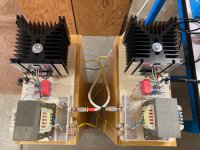
I built them into Arch Nemeses and I think they sound quite good.