Very nice that you make the experiment. And you are not demotavited by people who say, it is cheaap, it is not audio-phile, whatever.
Even if they will make medium quality OPT, sure they will make good chokes.
Even if they will make medium quality OPT, sure they will make good chokes.

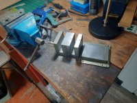
Making bobbins next 🙂sure they will make good chokes.
Attachments
But winding capacitance increases in a long coil...As long as you are already dealing with welded I and E sections, you could strap two E sections together with twin bobbins. This allows symmetrical windings for P-P OTs and also lowers leakage L. Long winding layers make the leakage paths long and thin, so the flux prefers to stay in the high mu steel. (since the leakage path is not shorter) If you don't need twice the size OT, then split one E section in two.
For twin bobbins and P-P you want to put primary winding halves on each bobbin so each winding section is effectively full length.
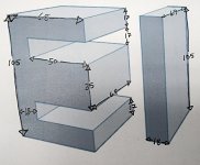
I rounded all dimensions to the nearest mm. This is the full block of iron. On the half-height, the only change is that the 69mm dimension becomes 34mm. The impedance ratio that I'm going for here is 2400:24, but I'd like to be able to make different ones as well. Can you point me to a resource or calculator that can teach me how to do this? I tried searching for the Crowhurst papers, but most of what I found were broken links.This one is completely understandable and I agree with you.
As for the ringing waveform, remember the waveform shape is part of the circuit. Before you start designing for a better waveform if this is your aim, you need to define the working conditions of the transformer first.
Interleaving reduces leakage inductance by a square factor. This is demonstrated in Crowhurst papers. Remember the more your primary turns are, the more you need to interleave to keep the same leakage inductance value.
There are two types of resonances. The peak and the dip. The first is easier to fix, the dip is your worst enemy resonance. The dip usually occurs from series connected secondaries with different capacitances to primary layers. Paralleling secondaries acts as a shunt and shifts this resonance above. Rule of thumb - parallel secondaries that are physically far away and leave series secondaries that are close to each other and there is no or little capacitance difference between them.
Give me some info on the core, surface area, window dimensions and impedance ratio and I can give you a useful interleaving schematic.
Attachments
Last edited:
Thank you. Before this is over, I hope to have something that's better than just "good enough." Maybe I won't get there. Who knows. But it's good to at least try.Very nice that you make the experiment. And you are not demotavited by people who say, it is cheaap, it is not audio-phile, whatever.
Even if they will make medium quality OPT, sure they will make good chokes.
I am sure you could make a choke for a Mofo amp.Thank you. Before this is over, I hope to have something that's better than just "good enough." Maybe I won't get there. Who knows. But it's good to at least try.
Oh yeah. That's on the agenda too. Going to be a big, bad honking thing too.I am sure you could make a choke for a Mofo amp.
A 24R secondary load?I rounded all dimensions to the nearest mm. This is the full block of iron. On the half-height, the only change is that the 69mm dimension becomes 34mm. The impedance ratio that I'm going for here is 2400:24, but I'd like to be able to make different ones as well. Can you point me to a resource or calculator that can teach me how to do this? I tried searching for the Crowhurst papers, but most of what I found were broken links.
Well, by rough estimation this core can be used at least for a 300B OPT. I could try to go even far and sketch a GM70 OPT. Are you sure you want to drive headphones?
That's just what I'm doing for the test setup. I want to branch out afterward and try other impedances. I've broken the laminations apart on a couple of other transformers so that I can interleave them. Same dimensions that I posted earlier. Can you do one for 2 EL34s in PP? I happen to have a few of those laying around, so I can build a test setup without buying anything else and then post the results. Much more complicated to wind, but a more thorough test of capabilities, I would think.Well, by rough estimation this core can be used at least for a 300B OPT. I could try to go even far and sketch a GM70 OPT. Are you sure you want to drive headphones?
I think that would be about 6.5k impedance on the primary. And likely 8R on the secondary would be fine.That's just what I'm doing for the test setup. I want to branch out afterward and try other impedances. I've broken the laminations apart on a couple of other transformers so that I can interleave them. Same dimensions that I posted earlier. Can you do one for 2 EL34s in PP? I happen to have a few of those laying around, so I can build a test setup without buying anything else and then post the results. Much more complicated to wind, but a more thorough test of capabilities, I would think.
That's just what I'm doing for the test setup. I want to branch out afterward and try other impedances. I've broken the laminations apart on a couple of other transformers so that I can interleave them. Same dimensions that I posted earlier. Can you do one for 2 EL34s in PP? I happen to have a few of those laying around, so I can build a test setup without buying anything else and then post the results. Much more complicated to wind, but a more thorough test of capabilities, I would think.
You also need to specify: triode, pentode, mode UL, CFB, local feedback.
Okay. Lets shoot for UL, 400v B+, 40mA quiescent and no feedback. What did you mean by "CFB"? Cathode feedback? I've never messed with that, so if yes then I'd say no.You also need to specify: triode, pentode, mode UL, CFB, local feedback.
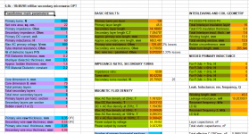
At first sight, you can get ~55W of output power if we assume the saturation begins at 1.2T. I have no knowledge on these cores.
You will get a calculated leakage inductance of 10mH with 4 primary and secondary interfaces and an acceptable interleaving for that is P4-SSSS-P8-SSSS-P4.
In this example I took into consideration trifiliar secondary windings, each third representing a 1R secondary impedance. That allows for 1R, 4R and 9R output impedances and even higher if you decide to split secondary packages. For a single 8R it will be simpler of course, but a different wire gauge.
Primary inductance will depend on your permeability, which you have to find out on your own.
I allowed ~3mm for windings bowing.
If you're ok with such design I will continue with the interleaving scheme.
Attachments
Wow, yes. That should work just fine for me. You seem to very much know what you're doing. Thank you for your contribution on this.At first sight, you can get ~55W of output power if we assume the saturation begins at 1.2T. I have no knowledge on these cores.
You will get a calculated leakage inductance of 10mH with 4 primary and secondary interfaces and an acceptable interleaving for that is P4-SSSS-P8-SSSS-P4.
In this example I took into consideration trifiliar secondary windings, each third representing a 1R secondary impedance. That allows for 1R, 4R and 9R output impedances and even higher if you decide to split secondary packages. For a single 8R it will be simpler of course, but a different wire gauge.
Primary inductance will depend on your permeability, which you have to find out on your own.
I allowed ~3mm for windings bowing.
If you're ok with such design I will continue with the interleaving scheme.
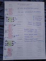
Here you go with a first scrap.
Calculated winding window height is 15,4mm, which is on the dangerous side - you might to be careful with bowing or clamp press the coil before inserting it into the core. Bobbin thickness of 1.5mm is taken into consideration.
The secondaries permit a 4R and 9R commutation. If you need only 8R, you can replace the secondaries with 3x2 paralleled layers of 73 turns 0.6mm wire.
Attachments
Thank you for doing that. I hope I can get it to fit on the core. It'll be a couple of weeks before I can get it done. Takes a day to wind one of the previous ones, and I'm only available to work on them on the weekends. I'm also going to redesign the bobbin to get a bit more room. The most recent one is 3mm thick.Here you go with a first scrap.
Calculated winding window height is 15,4mm, which is on the dangerous side - you might to be careful with bowing or clamp press the coil before inserting it into the core. Bobbin thickness of 1.5mm is taken into consideration.
The secondaries permit a 4R and 9R commutation. If you need only 8R, you can replace the secondaries with 3x2 paralleled layers of 73 turns 0.6mm wire.
I'm thinking of redesigning it with less layers, hence turns, a bit less power output, but higher chances it will fit.
That looked like a lot of work, so I'm just happy you took the time. So it's totally up to you how you want to proceed there.I'm thinking of redesigning it with less layers, hence turns, a bit less power output, but higher chances it will fit.
- Home
- Amplifiers
- Tubes / Valves
- Upcycling Microwave Transformers into Output Transformers