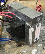
I messed with few microwave transformers. There are two problems: 1) if you salvage them from junk microwaves, they are all different sizes and construction, so it is difficult to find a pair of the same kind. 2) typically, laminations are thick, like 0.5 mm, compared to 0.3-0.35 mm of regular power transformers. So, they are not the best choice for output transformers.
Separating laminations - just forget it, there are multiple welds that keep the core together.
These transformers are good for power supply chokes. HV winding can be recycled for this purpose, need to add another winding to replace the primary and magnetic shunts.
Separating laminations - just forget it, there are multiple welds that keep the core together.
These transformers are good for power supply chokes. HV winding can be recycled for this purpose, need to add another winding to replace the primary and magnetic shunts.

One of the transformers I dismantled had a cross section area of 23.63 square cm, this is the distance across the tongue of the "E" multiplied by the size of the stack in cm. The transformer was wound at 1 turn per volt.
Using the calculator at. https://www.apogeeweb.net/tools/maximum-flux-density-bmax-calculator.html
and entering:
RMS voltage = 1 Vrms
Frequency= 0.000050 MHz (50Hz)
Number of turns = 1 (1 turn per volt)
Cross sectional area = 23.63 cm^2
press calculate
the given flux density is 1.9 Tesla
It can be seen these cores are run at a very high flux density so the steel must be capable of doing so.
The cores run hot as they are pushed so hard, remember these run at about 1000 watts.
Years ago I remember solving the issue of hum in a commercial audio product by simply using a slightly larger core in the power supply and reducing the flux density in the core to about 0.9 tesla. If you push the the transformer core hard in a audio device the external "B" field becomes a major problem.
When I eventually get around to testing one of these cores in a SE tube amplifier I shall gap it for best results when testing the amplifier, it is easy to do as the "I" can easily be removed and another paper spacer fitted.
For push pull operation I expect simply clamping the "I's" to the "E's" will suffice as some small amount of DC offset often exists with most designs.
For single ended operation I'm guessing the quiescent current should produce a flux of about 0.5 Tesla in the core, this will be determined by testing.
Apart from, or in addition to what has been said yet, I'm somewhat sceptical about the steel quality of those transformers. Main property seems to be that they need to be welded. But is this necessarily in conformity with high quality GOSS for example?
Best regards!
Best regards!
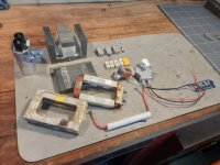
Lots of variation from one microwave oven to the next - but here's a typical salvage haul:
- transformer iron;
- two windings (all copper in this case);
- the winding from the fan motor (a low current choke);
- assorted power resistors and an X2 cap;
- one big cap (these measure well up to 20kHz);
- a high voltage fuse holder;
- three good switches; and
- one low-speed AC synchronous motor (for the platter).
Attachments
This is the typical prey of a microwave oven, lacking the magnetron's heater winding and the HV diode. Now have a close look at the HV filter capacitor, please, and note that it's paralleled internally by a resistor in the MΩ range. Sadly pretty useless, isn't it?
Best regards!
Best regards!
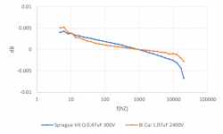
Maybe - though they measure OK at audio frequencies, big internal resistor included. Attached is a plot showing deviation of measured capacitance (in dB) from the measured capacitance at 1kHz. Compared are a 0.47uF 300V Sprague Vitamin Q and a (typical) high voltage cap retrieved from a microwave (branded Bi Cai, 1.07uF 2400V).Now have a close look at the HV filter capacitor, please, and note that it's paralleled internally by a resistor in the MΩ range. Sadly pretty useless, isn't it?
Attachments
Yes, the internal resistor surely won't impact the capacitor's AC behaviour, but it surely does compromise it's isolation properties.
Best regards!
Best regards!
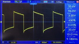
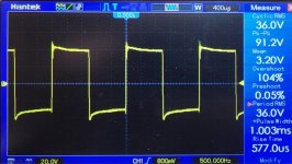
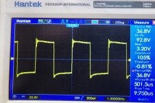
I took a couple of your suggestions and wound another transformer. This one uses the same iron as before, but the stack is 50% of the height as the previous version. I also changed the turns ratio to 2000:200. I kept the same 400-50 turns primary to secondary interleaving scheme. Definitely a different performance profile here. There's some ringing early on, and it's very apparent by 5 kHz. The square wave isn't rounded off anymore though. I still haven't got any feedback applied here. Any thoughts on what's up? It still sounds good to me. Not shrill by any means, but a little more crisp on the high end.
I have a vacuum chamber, and would like to at some point start potting the bobbins. Anyone have experience on what compounds to use? Wouldn't regular paraffin wax do the trick? I figured I could just put the bobbin in a can of melted wax, pull a vacuum to draw the air out of the windings and then pull the bobbin out to drip and cool. I would think that it would stabilize everything and help out with isolation. So many products these days are wicked expensive, and I don't mind old school if it works.
I'm also planning on winding a full piece of iron with as much #28 as I can cram onto it at some point and then measuring the inductance. Should be interesting.
Attachments
Last edited:
Remember that vacuum impregnation will screw up any low dielectric constant insulation. That applies for low density fibrous papers, meshes, etc. But it won't make much different for dense materials such as mylar, teflon, pressed paper, etc.
Before going for impregnation, you need to have a reason first. What is the reason you want to do it?
Before going for impregnation, you need to have a reason first. What is the reason you want to do it?
The main reason is insurance. There's the possibility that there's a loose turn or two in there since I hand-wound them. I did my best, but I'm not perfect. Potting would lock everything into place and make sure nothing wiggles around and breaks, wears off insulation, etc. I'm not as concerned about OPTs as I am power transformers though to be honest. I'd just feel better having that extra step isolating me from the mains. The only insulating material that I'm using for now is Kapton tape. That may change in the future though.
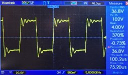
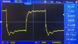
I noticed that swapping the leads on the secondary produced a different waveform still. Any suggestions on what I should try to help prevent the secondary from ringing on future iterations? Any instruction that I've found is in relation to stopping a factory secondary from ringing.. i.e. Snubber circuits, etc. Nothing about winding mistakes/ preventative techniques.
Attachments
Damping or snubbing the ringing can be used, certainly. But better approach is shifting the ringing frequency upwards, out of the audio band. For this purpose, self capacitance and leakage inductance should be reduced.
For lower self-capacitance, you can use "heavy" magnet wire, layer sectioning, and insulation between layers. For lower leakage inductance, interleaving.
For lower self-capacitance, you can use "heavy" magnet wire, layer sectioning, and insulation between layers. For lower leakage inductance, interleaving.
Okay. I saw the 4:1 interleaving ratio recommended somewhere else here on diyAudio, so that's why I've been going with that. Does the actual ratio particularly matter so long as you're interleaving? i.e. more interleaving = better? I read somewhere else too that Kapton tape can lead to excess capacitance. Still other places heavily recommend it. That's the problem with the internet. So much information, very little consistency. Either way, I'm planning on trying some different materials. I've seen mylar tape recommended, and I happen to have some glass fiber tape. Some people even say that they use paper masking tape. Not so sure about that one per se, but there it is anyway. Maybe it'd be better with wax impregnation. Then I've also seen rosin recommended for potting transformers. That would definitely be old school.Damping or snubbing the ringing can be used, certainly. But better approach is shifting the ringing frequency upwards, out of the audio band. For this purpose, self capacitance and leakage inductance should be reduced.
For lower self-capacitance, you can use "heavy" magnet wire, layer sectioning, and insulation between layers. For lower leakage inductance, interleaving.
Last edited:
The main reason is insurance. There's the possibility that there's a loose turn or two in there since I hand-wound them. I did my best, but I'm not perfect. Potting would lock everything into place and make sure nothing wiggles around and breaks, wears off insulation, etc. I'm not as concerned about OPTs as I am power transformers though to be honest. I'd just feel better having that extra step isolating me from the mains. The only insulating material that I'm using for now is Kapton tape. That may change in the future though.
This one is completely understandable and I agree with you.
As for the ringing waveform, remember the waveform shape is part of the circuit. Before you start designing for a better waveform if this is your aim, you need to define the working conditions of the transformer first.
Interleaving reduces leakage inductance by a square factor. This is demonstrated in Crowhurst papers. Remember the more your primary turns are, the more you need to interleave to keep the same leakage inductance value.
There are two types of resonances. The peak and the dip. The first is easier to fix, the dip is your worst enemy resonance. The dip usually occurs from series connected secondaries with different capacitances to primary layers. Paralleling secondaries acts as a shunt and shifts this resonance above. Rule of thumb - parallel secondaries that are physically far away and leave series secondaries that are close to each other and there is no or little capacitance difference between them.
Give me some info on the core, surface area, window dimensions and impedance ratio and I can give you a useful interleaving schematic.
Hi bondini,Lots of variation from one microwave oven to the next - but here's a typical salvage haul:
The iron will become a power supply filter choke. 🙂 If I find a pair of transformers of similar dimensions, I will be tempted to wind some output transformers. What's not to like?!?
- transformer iron;
- two windings (all copper in this case);
- the winding from the fan motor (a low current choke);
- assorted power resistors and an X2 cap;
- one big cap (these measure well up to 20kHz);
- a high voltage fuse holder;
- three good switches; and
- one low-speed AC synchronous motor (for the platter).
How did you do to extract the windings from the iron without damage the copper?
In microwave transformers that I messed with, windings were not solidly glued to core. After you open the core, a gentle tap is sufficient to loosen them.extract the windings from the iron without damage the copper?
In microwave transformer, both pri and sec windings are wound and impregnated as units, and then assembled with core.
As long as you are already dealing with welded I and E sections, you could strap two E sections together with twin bobbins. This allows symmetrical windings for P-P OTs and also lowers leakage L. Long winding layers make the leakage paths long and thin, so the flux prefers to stay in the high mu steel. (since the leakage path is not shorter) If you don't need twice the size OT, then split one E section in two.
For twin bobbins and P-P you want to put primary winding halves on each bobbin so each winding section is effectively full length.
For twin bobbins and P-P you want to put primary winding halves on each bobbin so each winding section is effectively full length.
Hi Alain,Hi bondini,
How did you do to extract the windings from the iron without damage the copper?
Over the years I have pulled apart 4 microwave oven transformers and each has been a little different. Twice it was easy to separate the Es from the Is, twice I had to cut them apart. Some windings fell out easily without damage, others were hard to remove and came out a little damaged, others I had to cut through and were destroyed (into the metal recycling!) All the laminations I have seen are 0.5mm thick. For one transformer, they fell apart easily (!) the others were held together solidly. I have used them to build power supply chokes for C-L-C filters. This thread may inspire me to build an output transformer!
- Home
- Amplifiers
- Tubes / Valves
- Upcycling Microwave Transformers into Output Transformers