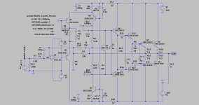
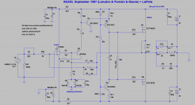
A curiosity: Wiederhold/Lomakin/Parshin derivative from 2016 with triple EF output, designed by T117
"If you want to build a really cool amp, that could sound better brand of amplifiers, you can build it for this schematics. This is a very simple amplifier, but there aren't many amps better than him.
1.The triple output stage is always needed, regardless of the type of VAS. This output stage has a high linearity. I do not offer a simple and bad decisions.
2. VAS contains 4 of the transistor. This is a very small number and this is the best solution how to get out of this small number of transistors is such good value of THD." - T117
Attachments
Last edited:
Can you make Blomley out of this triplet?
I don't have enough skills for that. Blomley has an unique non switching Class B sub-circuit (the first one in audio history?), maybe Elvee or Valery can answer your question. They have amount experiences in non-switching outputs.
Of #42 PM, part of scheme Q1, R19, R22, R23, R20, Q3 (Blomley).
Your scheme # 441, respectively Q8, R33, Q10
Your scheme # 441, respectively Q8, R33, Q10
Last edited:
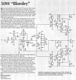
Bloomley Hartsuiker
If anybody is interested in buildable Blomley, here is modified Hans Hartsuiker version,
slightly improved, that at least sims ok.
It has symmetrical rails - primary reason I gave up on 'regular' Blomley..
From what I remember Blomley was a good candidate to add servo to it to control output DC offset..
Attachments
Last edited:
And if you screw the Wiederhold output to the Tr9.10 collectors?
Symmetrically so 🙂
Symmetrically so 🙂
Last edited:
If anybody is interested in buildable Blomley, here is modified Hans Hartsuiker version,
slightly improved, that at least sims ok.
It has symmetrical rails - primary reason I gave up on 'regular' Blomley..
From what I remember Blomley was a good candidate to add servo to it to control output DC offset..
minek, thank you for the sims, but frankly, it is neither promising, nor appears to surpass Lomakin & Parshin/wiederhold.
A run-of-the-mill Blameless can stand 1uF across the load without a sweat. I think that work around this interesting circuit and make It able to do the same, worth the effort. I'm talking the Wiederhold hex quasi.
A run-of-the-mill Blameless can stand 1uF across the load without a sweat. I think that work around this interesting circuit and make It able to do the same, worth the effort. I'm talking the Wiederhold hex quasi.
Agree. Quasi hexfet output, despite being "outdated" topology, can run very low quiescent current and tolerates easily the complex loads. Several years ago I have built a single channel Quasi NMOS200, with just a single pair output, set Iq somewhere 40mA, it sounded very good. However the drivers of FEts are critically. When I replaced 1381/3503 (or similar, I don't remember accurately what drivers was applied first) to MJE15034/35 the sound improved noticeably. More robust driver, more effortless sound. Perhaps because the output FETS and emitters of drivers are working on same load, so the latter can help the FETs in critical crossover region.
Put an RL filter on the output of the amplifier and you will not be afraid of the capacitive component

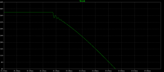
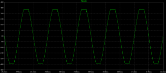
Also, even without LR, increasing values of C9/C12 (e.g. to 220pF) will improve response to capacitive loads.
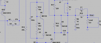
C16 makes it worse. Without it, response to capacitive loads is also better.
In my build I don't have C16.
C16 makes it worse. Without it, response to capacitive loads is also better.
In my build I don't have C16.
Last edited:
C16 is harmful. inductance 1i is small, put 2-4u. Well, the correction should be selected more precisely. The sound of this amplifier is incomparable with these simple amplifiers. Space
>1i is small, put 2-4u. Well, the correction should be selected more precisely.
1uH is small? I usually put 1uH + 4.7 Ohm damping resistor.
I just checked Douglas Self's book - from his practical experience he is recommending 2.3 uH inductor.
1uH is small? I usually put 1uH + 4.7 Ohm damping resistor.
I just checked Douglas Self's book - from his practical experience he is recommending 2.3 uH inductor.
2u-4 u.
Note the output filter in the SLA.
Page 9 in the attachment Сверхлинейный УМЗЧ с глубокой ООС.pdf - Google Drive
Note the output filter in the SLA.
Page 9 in the attachment Сверхлинейный УМЗЧ с глубокой ООС.pdf - Google Drive
Last edited:
That corresponds to at least:
a) 20 turns of 1.0 mm wire on a diameter of AA battery (14 mm).
b) 30 turns of 1.6 mm (14 gauge in US) wire
The thicker the wire - more turns needed.
It's better to use thicker wire.
I'm going to use 4.7 Ohm damping resistor with this coil.
a) 20 turns of 1.0 mm wire on a diameter of AA battery (14 mm).
b) 30 turns of 1.6 mm (14 gauge in US) wire
The thicker the wire - more turns needed.
It's better to use thicker wire.
I'm going to use 4.7 Ohm damping resistor with this coil.
Yes, to be adjusted on the real object.Well, the correction should be selected more precisely.
Interesting question in quasi design, is "Where to place temperature sensor Vbe multiplier transistor?".
In quasi, one half of the output is EF, the other half is CFP. Each of them need different tempco.
For one of them temp sensor needs to be placed on the output device, for the other one - on the driver.
So basically it's almost impossible to get it right for quasi design - that's why I wasn't overly concerned about using LED vs. 1N4148 diode in the spreader.
Luckily, it's a bigger problem for BJT outputs, not a big deal for Fets.
Correct location of BIAS Vbe thermal sensor
See this thread (E.g. post #10) for details - it's from several years ago, when I was building NMOS200 amp (just like Egra did).
Great amp, by the way. All in all, I built six of them 🙂
In this one, I'm planning to place Vbe spreader on the driver's heatsink.
What you guys think?
Last edited:
Well, lacking the know how for a scientific solution, I would try the driver heatsink on one channel, and the output device collector on the other, plus cabinet internal temperature for both solutions, and see what Happens.. ��
Last edited:
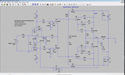
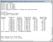
Here is LMK with few changes (2 resistors added around Q5).
FFT profile looks better.
Perhaps Maxim can tell if these changes make sense?
FFT profile looks better.
Perhaps Maxim can tell if these changes make sense?
Attachments

- Home
- Amplifiers
- Solid State
- Unusual amp from 1987