Hi famousmockingbird,
I will try to mod with your values tomorrow. Did you use simulation ?
When I made my trial by changing only the source resistor 1 K to 470 R I had a Vgk around - 0.7V (Cathode at 67.4 V and grid at 66.7 V) these are measured values. The calculated gain should be around 11 but I found the sound "bad".
Yes I simulated it.
The original circuit gain is around 10db. The gain with the source resistor value change of 470 is around 20db bringing your output voltage above the normal 1-2Vrms level possibly overdriving your amp/preamp.
The original circuit gain is around 10db. The gain with the source resistor value change of 470 is around 20db bringing your output voltage above the normal 1-2Vrms level possibly overdriving your amp/preamp.
Hi,
I made the modifications today according to famousmockingbird post. I do not have a 8.2 K for the drain resistor and I managed to make a 7.8 K instead. Measurements show that Vgk is around -1V. I connected then the cdp to my amp and the sound was.............................GOOD !!! Much better than before, less bummy. This is my first feeling it needs to be confirmed with more listening time.
The morale of the story is that dust cleaning a hifi gear makes me realize that I listened to distorted sound from many years and found it very good. I will suggest a friend who also owns a cdp tweaked by the same tweaker to dust clean his cdp too and draw the schematic of its cdp output stage !
People on this forum are very smart, you have been very helpful thanks a lot,
Swap them. 🙂
Would this hold?
An externally hosted image should be here but it was not working when we last tested it.
An externally hosted image should be here but it was not working when we last tested it.
If Uinp=0,5V the Load Line Simulator predicts 0,5x15,9= 8V out from the triode when Rk is left unbypassed. In the voltage devider 75% of the signal is lost (8K/32K) and gets biassed by 8/128 volt.
I know too little from those freaky semi's to make further adjustments, so I maintained the 3V bias. This would probably make a unity gain stage..
The triode produces 2H depending on input level.
I know too little from those freaky semi's to make further adjustments, so I maintained the 3V bias. This would probably make a unity gain stage..
The triode produces 2H depending on input level.
Two gain stages is too much. Use the MOSFET as a source follower direct coupled, basically just the MOSFET and tube switching places in the first schematic (and resistor values appropriately changed). Less level shifting, one less coupling capacitor, no amplifying and then reducing, and less injected noise from the power supply.
We are not that smart; it's just that some tweakers don't understand basic electronics.
I am not so sure that the tweaker from whom I got my cdp did not understand basic electronics as you said, he was well lnown in my area in the 80's. I guess that his business policy was to make something that sound completly different and he had some success at that time.
Before posting I made some mods but did not succeed I am the one who do not understand basic electronics that's why I am here to learn.
People here are smart some more positive than others 🙂
Maybe something more like this?
Operating points:
6922 tube
Va 72.8
Vk 1.5
IRF630
Vd 128
Vg 72.8
Vs 68.9
Operating points:
6922 tube
Va 72.8
Vk 1.5
IRF630
Vd 128
Vg 72.8
Vs 68.9
Attachments

Last edited:
Ok, the semi has probably unity gain and the triode 13 times.
What voltage is offered at the grid?
Ri would be 5K, how about PSRR?
What voltage is offered at the grid?
Ri would be 5K, how about PSRR?
Nice work. I didn't finished yet modding my cdp according to famousmockingbird simulations may be today I hope so.
I wonder how is the sound of these 3 arrangements : Tube/Tube - Tube/Mosfet - Mosfet/Tube.
Do they sound different or they all sound the same ? Can your simulations give the answer, may be by looking at the distortion figures ? I have the feeling that Tube/Tube and Mosfet/Tube configurations will give more "tube sound" than the tube/Mosfet
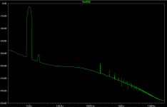
Here are some images from the simulations I did the other day.
@1kHz "NVD33ffta.png" is before modifications and "NVD33fftb.png" is after. Clearly much better results for the latter circuit.
I somehow lost the files for the the 6922-->IRF630 circuit I posted 😕 I will redo it and post the results
@1kHz "NVD33ffta.png" is before modifications and "NVD33fftb.png" is after. Clearly much better results for the latter circuit.
I somehow lost the files for the the 6922-->IRF630 circuit I posted 😕 I will redo it and post the results
Attachments

Right FFT is much better in terms of distortion. Some enjoy a 'rich' sound, obtained from elevated second harmonic. A triode as cathode follower does not add to the harmonic spectrum (if soundly biassed). A triode can produce 2H if used as a voltage amplifier, that's what's meant in #3, especially when operated at the brink of grid current near 0V bias.
That is a question which cannot be answered, as the issue is not the device used but how it is used and what precedes and follows it. Tubes/MOSFETs/BJTs don't have a "sound", but poorly designed circuits containing them will have a sound - some like this, some prefer to avoid it.NVD33 said:I wonder how is the sound of these 3 arrangements : Tube/Tube - Tube/Mosfet - Mosfet/Tube.
Note that real life is more complicated than simulations, so simulated distortion figures should be taken as a very rough guide only.
Hi everyone,
Modifications completed here are the measured values for right and left channels:
- Vgate : 11.85 - 12.00
- Vsource : 8.55 - 8.67
- Vgrid : 60.5 - 59
- Vcathode : 61.7 - 60.3
How it sounds now? It sounds very good indeed, very detailed, etc...I love this sound too but it sounds more or less similar to another good sounding cdp.
The difference between the two circuits that I felt immediatly is the feeling of power, with the original circuit the music seems more powerful, it is like that the orchestra, artists are throwing all their energy into the music, I hear more distinctly the play of the bass guitar for instance and this makes you tap your feet. Presence of more bass, or H2 ?
it's difficult to put words to describe the sound, this is my first feeling do not take it as gospel.
As stated before the simulation distortion results are not real world results and only should be used as a rough guide. With that being said the original circuit or at least on my simulation shows 2% THD, which in my opinion is what the original tweaker intended, end result is coloration of the audio and definitely not high fidelity. The current modified circuit shows only .02% THD in the simulation, so the audio is colored much less by distortion....or think of it as purer.
The only other thing I could think of is that you mentioned increased bass. This could be a result of changing the 33k resistor to 10k......the input high pass filter corner frequency has moved up a bit. Unless somebody can correct me it's still below 10Hz and shouldn't be audible.
The tube--->mosfet circuit which has been recommended by several people on here imho would be worth a try. As far as distortion this will give you the h2 you want, my simulation shows .16% THD. This is the best of both worlds, you get some harmonic distortion but not a gross amount from the triode gain stage and you get a better output buffer with the common drain output stage....win win.
There is no right or wrong just try not to blow anything up, get shocked, or start a fire and a trust your ears.
Hi,
Now I am listening to the cdp, no risk to start a fire or get shocked thanks to you famousmockingbird you have been very helpfull I have learned interesting things.
imho they do have a sound. Everything being the same, if I swap amplifiers (BJT/MOSFET) the sound changes. my amps are from well known brands and should be correctly designed.
Now I am listening to the cdp, no risk to start a fire or get shocked thanks to you famousmockingbird you have been very helpfull I have learned interesting things.
Code:
Tubes/MOSFETs/BJTs don't have a "sound", but poorly designed circuits containing them will have a sound - some like this, some prefer to avoid itimho they do have a sound. Everything being the same, if I swap amplifiers (BJT/MOSFET) the sound changes. my amps are from well known brands and should be correctly designed.
The most likely cause of a difference in sound between two competently-designed power amplifiers is a small difference in frequency response or output impedance.
The most likely cause of a difference in sound between two competently-designed power amplifiers is a small difference in frequency response or output impedance.
Or level. Most amateurs don't bother with the fiddly necessity of getting a <0.1dB match. At small level differences, our perception tells us that the louder amp sounds "clearer" and "more open."
Yes I am aware of the effect of the level, it is very important when performing immediate AB listening test.
I meant swapping my amps, it is for a certain time (1 to 3 months, maximum every 3 months I swap an equipment in my system ). Level effect is less important in this case.
When comparing 2 equipment (not a cheap one versus an expensive one but both at same level of manufacture quality, price, etc...), one is sounding "harsh", "analytical or clinical" etc...and the other is sounding "warm", "analogue" etc..., from what I have learned here with my tweaked cdp ---> modified according to famousmockingbird simulations, I wonder if the difference in sound is simply a matter of distorsion ? In short, to make the sound sounds "good" just distort it in an adequate manner.
- Status
- Not open for further replies.
- Home
- Amplifiers
- Tubes / Valves
- Unsual use of triode?