Hi,
I have an old modified CD player with hybrid ouput stage (IRF630 and E88CC). The player is working well and the sound is nice.
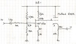
I opened it for dust cleaning and was curious about the ouput stage so I draw the schematic (one channel shown).
I have no question about the IRF but the cathode follower tube stage puzzles me since the grid voltage is the same or slightly positive with respect to cathode voltage. I made the measurements many times to make sure.
Could someone have an explanation for this unusual use of triode?
I have an old modified CD player with hybrid ouput stage (IRF630 and E88CC). The player is working well and the sound is nice.
I opened it for dust cleaning and was curious about the ouput stage so I draw the schematic (one channel shown).
I have no question about the IRF but the cathode follower tube stage puzzles me since the grid voltage is the same or slightly positive with respect to cathode voltage. I made the measurements many times to make sure.
Could someone have an explanation for this unusual use of triode?
Attachments
Yes. This seems designed for 'tube sound'! Better (i.e. more accurate amplification, lower output impedance) results might be obtained by using the valve as a voltage amplifier and the FET as a follower - and choosing wiser bias points.
Thanks for your replies. I will read the article given by the link carefully.
I replaced the IRF source resistor (1 K) by a variable resistor and played with. When I reduce the IRF source resistor then grid and cathode voltages reduce also but stayed in the same way until the variable resistor reached around 500 R the grid voltage became lower than the cathode voltage. I set the variable resistor value to 470 R, the grid voltage is then around 0.7 V below the cathode voltage. I made then a listening test and the sound was harsh, lacking of bass...in short not good. I reverted the variable resistor value to 1 K and the sound is OK.
What do you think if this time I increase the IRF drain resistor (5.6 K) to 10 K for instance? I do not have at hand a variable resistor than can disspipate 2W
Member
Joined 2009
Paid Member
As I am new to tube I prefer not to touch this part of the schematic before exploring all the possibilities on the IRF side. After that the next step would be changing cathode resistor.
The basic design is wrong. The valve needs at least 50-60V across it. Then it will act as a transparent buffer. To achieve this means redesigning the first part, or using AC coupling.
As I said I am new to tube, this schematic was unusual to what I have learned about triode and wanted to understand, I do not have enough knowledge to redesign anything. Furthermore this CD player is working fine I do not want to damaged it. May be I will have the answer one day.
Thanks to all for taking your time replying to my post.
Thanks to all for taking your time replying to my post.
It's not an "unusual" use of a triode. It's a cathode follower, direct coupled (no coupling capacitor) to the preceding stage. The ECC88 is operating near zero bias. Very bad choice of operating points, unless you are wanting to add lots of 2nd and 3rd harmonic distortion, which looks to be very much the case here IMHO.Could someone have an explanation for this unusual use of triode?
Hi,
Thanks for the explanations. Ok for direct coupling, but triode operating near zero bias is new for me, never seen it before.
I am afraid you are right about distortion, i must find a way to measure it.
My tweaked cdp sounds good to my ears because of distortion then this tweaked cdp cannot be said "hifi" since hifi is suppose not to distort the input signal right? Could this schematic possibly a guitar amp schematic?
Operating a triode at near zero bias is usually a bad idea, which is why you rarely see it. It is most likely to crop up in low supply rail circuits (such as cathode follower 'tube buffers' fed from +12V) or poorly designed circuits (like this one) which leave too little anode-cathode voltage across the valve.
It is a bad idea because the triode will take grid current, which is quite non-linear. Only OK if either the previous stage has a low output resistance or you actually want some distortion.
It is a bad idea because the triode will take grid current, which is quite non-linear. Only OK if either the previous stage has a low output resistance or you actually want some distortion.
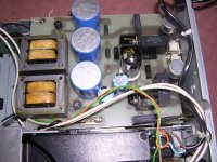
From previous posts I understood that operating a triode at near zero bias is a bad idea. But this schematic is not in my brain but the cirduit exists (see picture). The tweaker of this cdp is now retired I cannot get in touch with him.
I would like to try some modifications to make the triode operate in a more usual way while having a good sound from the circuit. I do not want to damage my cdp which is working well and dust cleaned now. Could some one suggest an easy mod to do ?
I would like to try some modifications to make the triode operate in a more usual way while having a good sound from the circuit. I do not want to damage my cdp which is working well and dust cleaned now. Could some one suggest an easy mod to do ?
Attachments
You need to modify the first stage so that there is more voltage across the valve. This means increasing the values of the source and drain resistors, and adjusting the input bias network accordingly. Finally drop the value of the cathode resistor a little, in order to maintain a similar current. Essentially the value of almost every resistor has to change, but you can leave the circuit architecture as it is.
Actually ... (at DF96) doesn't it mean just changing the drain resistor on the FET? Presently, its set as a 5.6x "unbypassed source bias" multiplier. Ja, Ja, the world isn't so simple, but it is close. However, the 10K || 33K || 470K input network is a modest (2.5 dB) gain reducer. Overall, I expect it to peg at a fixed 3.5x or 10 dB gain network.
Changing the 5.6K drain/gain resistor to 11K accomplishes everything you want: FET stage gain increases to something closer to 10x. The drain would be at about -55V from rail, or 70V plus or minus. This increases cathode-anode voltage on ECC88, per your recommendation. The grid will work closer to relative-negative bias, and the "tube sound" of that crossover region will be reduced. Net? Cleaner output.
I might change the 33K input ground-pulling resistor to 15K, just to counteract the increased gain, so that the stage operates as a drop-in-of-no-particular-downside. Hell... if the experimenter was curious, it'd be fun to drop in an DPDT switch, to use "original" versus "modified" components, for A-B testing. And the 15K substitute would be replaced with a 25K pot, so that the actual value could be trimmed so the stage is acoustically "exactly the same gain", for best A-B comparison.
GoatGuy
Hi GoatGuy,
Thank you for your input, you said exactly what I wanted to hear!
I have already made a trial but reverted back because I found the sound not good. May be my ears are accustomed to the distorted sound from this cdp and less distorted sound is bad sound by me.
I will make the mods and feedback.
Thank you for your input, you said exactly what I wanted to hear!
I have already made a trial but reverted back because I found the sound not good. May be my ears are accustomed to the distorted sound from this cdp and less distorted sound is bad sound by me.
I will make the mods and feedback.
It is generally a bad idea to increase gain, then increase attenuation too. That is why I suggested changing almost every resistor.
It is generally a bad idea to increase gain, then increase attenuation too. That is why I suggested changing almost every resistor.
I completely agree with this statement. Resistors are cheap and there is only a handful of them so not really too much work to achieve better results.
My brain still wants to reverse these two stages, use the tube for voltage gain and the FET for the output.
Hi,
I have an old modified CD player with hybrid ouput stage (IRF630 and E88CC). The player is working well and the sound is nice.
I opened it for dust cleaning and was curious about the ouput stage so I draw the schematic (one channel shown).
I have no question about the IRF but the cathode follower tube stage puzzles me since the grid voltage is the same or slightly positive with respect to cathode voltage. I made the measurements many times to make sure.
Could someone have an explanation for this unusual use of triode?
Swap them. 🙂
I might change the 33K input ground-pulling resistor to 15K, just to counteract the increased gain
Wouldn't you have to change the 470k value as well?
If you change the bias resistor values from 470k to 100k and 33k to 10k, and also change the Drain resistor to 8.2k you should have about the same gain as before but now your drain voltage is 65v putting your cathode follower Vgk at -1.4.
- Status
- Not open for further replies.
- Home
- Amplifiers
- Tubes / Valves
- Unsual use of triode?