I'm hoping to get started on mine here in the next week or two; now that George has released the beta board I've been trying pretty diligently to get to a pause point in another project so I can get back to tubes, and I think I got there today.
I think I should have all the parts in stock except the little pFET.
I think I should have all the parts in stock except the little pFET.
I would imagine that any TO-92 p channel fet with a compatible pinout will work. I used the BSS84 in my original simulation because it was in the LT spice library. Once it became time to actually build something, I ordered a bunch of small fets. The first one I tried was the VP0106 which worked fine, so I never tried any of the others.
I got some new mosfets from Mouser and Digikey, with more on their way from the UK. I also got some 600 volt electrolytics that (barely) fit in the board so a "go big or blow up" test session is in my future. All will be subjected to some serious abuse including my lousy guitar playing.
I got some new mosfets from Mouser and Digikey, with more on their way from the UK. I also got some 600 volt electrolytics that (barely) fit in the board so a "go big or blow up" test session is in my future. All will be subjected to some serious abuse including my lousy guitar playing.
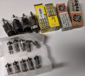
These showed up in the mail. 8 6DQ5 and 10 6J51P tubes for the UNSET build. Hopefully they will deliver the goods. The long lead item in all this for me will be the OPTs. What OPT specs should I be targeting with these tubes if I am looking to do a easy 12-15W build? Something like the Edcor CSXE25-5K or the Toroidy TTG-EL82SE?
Attachments
It would be good to hear George’s latest experiments and findings on suitable output transformers for UNSET. Sounds like most of his work to date used a 5k Hammond with 8 Ohm speakers connected to the 16 Ohm taps (reflecting 2.5k primary).
Meanwhile, I looked into the Toroidy offerings and now have a pair of TTG-KT88SE waiting. These have a 3K primary which may be more suitable than the TTG-EL84SE with 5K. Both of these are specified for >150 ma, while the TTG-EL34 at 4k primary sports only 100 ma (if the spec sheets do not contain a typo).
Meanwhile, I looked into the Toroidy offerings and now have a pair of TTG-KT88SE waiting. These have a 3K primary which may be more suitable than the TTG-EL84SE with 5K. Both of these are specified for >150 ma, while the TTG-EL34 at 4k primary sports only 100 ma (if the spec sheets do not contain a typo).
Due to limited budget I have been experimenting with tubes and transformers that I already have.
I have a wide variety of tubes in sizes from tiny (the 9 watt 6GF5 and the 10 watt 6DG6) to the 40 watt 6LW6. Most of my testing has used the 26LW6 and the 26HU5. Despite the different ratings these appear to be the same tube. They appear to be interchangeable in the UNSET board, and male the same power output. The 26HU5's are usually cheaper. Stan (ESRC) had about 400 of them in stock when he passed, and would sell them to me, a long time customer (I also bought tubes from Stan's father long ago) for $10 each in 25 quantity. I realize that many will use tubes in the 6DQ5, 6CD6, 6CB5 size class, so that's where I will go next.
I have a pair of 2006 vintage Hammond 1628SEA's, a pair of Edcor CSXE25-5K's from 2004 or 2005 when they were bright metallic blue colored (universally hated), two or three pairs of Transcendar custom "300B OPT's" that I got around the same time frame, and pair of Toroidy TTG-KT88PSE transformers that I got about 2 years ago.
The Hammonds are the largest, and the lossiest transformers that I have they waste 10 to 15% more power than the big Edcors, when wired for the recommended 5K ohms. They however are rated for 30 watts, and I have set out to build something that will get 30 watts out of them. They are rated for 125 mA max, but to get 30 watts out of them, I need about 130 to 140 mA. I can not get 30 watts from a single 40 watt tube, so two 26LW6's or 26HU5's are run in PSE. 30 watts takes 660 volts of B+, and 65 to 70 mA per tube. This makes the Hammonds kick butt. 30 watts is available from 20 Hz to 20 KHz with 7.6 % THD at 20 Hz (saturation visible) but 2.01% at 50 Hz, 1.54 % at 1 KHz, and 5.79% at 20 KHz. Attempts to get 30 watts at 2.5 K ohms proved futile.
The Transcendars have not been tested yet, but they are much smaller, probably good for the 6DQ5 sized tubes. I have them in my SSE, and they rock at 10 watts.
Previous testing with the Edcors show a slight loss at 20 Hz, and gain at 20 KHz. They will see power soon.
The Toroidy's have been a disappointment in bench testing. They are 1500 ohms, and intended for two 300B's or two KT88's in parallel. The spec sheet states "Nominal power 60W" and "Nominal anode current 300 mA." I am running two 26HU5's in PSE on 450 volts. Tube current is set at 125 mA per tube. With the 1500 ohm load I have no problem getting 40 watts at 1.5% THD at 1 KHz, and 35 watts at 25 KHz at 2% THD. Attempts to drive the amplifier at 20 Hz results in excessive tube current and a super distorted output that refuses to go above 1 watt no matter how hard I drive it, or what I set the bias current at. Lower currents result in lower distortion but anything over half a watt at 20 Hz is distorted at any idle current. Something resembling a sine wave at 5 watts of power requires frequencies above 80 Hz.
I reconnected the Toroidys at 3K ohms by using the 4 ohm tap on an 8 ohm load. This improved the situation a lot. Again on 450 volts, I got almost 40 watts with much less tube current, about 70 to 90 mA. As expected the saturation was far better. I could get 10 watts at 20 Hz, but it was still quite distorted at 19%. At frequencies above 70 Hz 25 watts or more were available at 3% or less THD. My Yamaha NS-10M Studio monitors have virtually zero response below 70 Hz, and the impedance is in the 20 ohm range at 70 Hz, so these OPT's may sound far better than they measure on the NS-10's. These speakers have been driven by an SSE or a "Tripath" chip amp (switch selectable) for most of their life, The UNSET will replace the SSE.
I plan to test the Toroidy's and the Transcendars on 300 ohms with smaller tubes in the near future.
The Toroidy's have been a disappointment in bench testing.
I thought SE OPTs had to have an air gap and that toroidal OPTs don't. Is that not the case?
The short answer to your question is that most toroidal transformers used as SE outputs are in fact air-gapped. There had been several threads on diyAudio on the topic of toroidal transformers as SE outputs. See for example:
Problem - SE Class A with toroidal OT ?
In one of the threads a diyAudio member reported that Toroidy had replied to inquiry that their SE output transformer cores are gapped. Based on the good performance and experience with PP output transformers from Toroidy one could expect at least competent performance from their SE line. I purchased a pair of Toroidy TTG-KT88SE (3k primary) for use in my UNSET build that will start as soon as George releases the parts list, so I sure hope the issue that George experienced with his TTG-KT88PSE (1.5k primary) could be worked out.
I’m puzzled by the improvement he observed when using it to reflect 3k primary, compared to the normal connections for 1.5k primary. Does that mean the UNSET connected 26LW6 pair performs better at a higher loads? Do we have real curve traces for a combination 26LW6/Mosfet device to determine loadlines?
Last edited:
Have you posted anywhere about the way to determine the values for the G2/G1/Gnd divider?
Most of my testing has been done with 300K (2 X 150K in series) from plate to grid and 30K to ground. This seems to be a good place to start with nearly every TV horizontal sweep tube that I have tried.
Raising the value of the 30K grid to ground resistor will increase the amount of feedback lowering the THD of the output stage. It also raises the amount of drive required to get the same output, and shifts more of the total dissipation from the tube to the mosfet. The mosfet / heat sink pairs that I am using get to about 60 degrees C with big tubes and 600 volts with 30K. I had a small fan on the sinks as I tried 33 and 36 K.
I don't know the "breaking point" of the P channel mosfets That I am currently using, so I am hesitant to push them much harder until I can rig up a method to make them a bit easier to change. I have several new fets to test and some are TO-247's due to the TO-220's being out of stock, but the board only accepts TO-220's.
I thought SE OPTs had to have an air gap and that toroidal OPTs don't. Is that not the case?
Vanderveen came up with a distributed gap toroidal OPT design that was used successfully by Plitron and Amplimo for many years. Neither of these are currently available, and Vanderveen is currently selling his own brand of toroidal OPT's for both SE and P-P applications. It has been strongly suggested that Toroidy is doing something very similar, but it is not explicitly stated just how they are made.
Regardless of the methods, you still can't beat physics. The Toroidy's weigh 2.7 kg. The Transcendar's weigh 2.5 kg. The Hammonds weigh about 5 kg. Guess which one makes the most power at 20 Hz. On the flip side of this, the Toroidys have the least loss, and flat HF out to past 40 KHz. On most speakers that are typically used with a SE tube amp the Toroidy's should win a listening contest.
The Toroidy's that I have may state 60 watts nominal, and 300 mA nominal, but they are designed for a "pair of 300B's" or a "pair of KT88's." Without beating them too hard a pair of either tube will get you about 20 watts, and need about 150 mA on 400 to 450 volts to get there. The Toroidy's may work fine at this level, I haven't tried them there yet.
I’m puzzled by the improvement he observed when using it to reflect 3k primary, compared to the normal connections for 1.5k primary. Does that mean the UNSET connected 26LW6 pair performs better at a higher loads? Do we have real curve traces for a combination 26LW6/Mosfet device to determine loadlines?
I have not tried to trace out curves for the mosfet / 26LW6 combo. I may try to do that once I have tested all of the new P-channel fets that I have collected to find the best choice going forward for the fet.
The current 9P25 fet is not specified for continuous operation in the linear region, and ON / Fairchild data sheets have proved untrustworthy in this respect with other parts. There has only been one failure so far and it was due to a full power square wave oscillation at 40 KHz. It still may be the best choice, but only some serious testing will tell for sure.
I have achieved roughly similar power outputs and efficiencies at 1KHz with 1500 ohms on about 450 volts, and 5000 ohms on 660 volts if I take the 10 to 15% extra loss of the Hammond OPT's into consideration. I am currently a bit short on 3000 ohms, but the Transcendars are probably the limiting factor here due to their high DCR and associated copper losses.
Most of my testing has been done with 300K (2 X 150K in series) from plate to grid and 30K to ground.
I had it completely wrong. I was carrying around a memory of seeing a sketch and without realizing it, it morphed into a crazy drive G2/R/G1/R/Gnd. setup. Or my version of one anyway. Finding your post, I see. Thanks!
I started a new thread for the Beta board build, and for turning those boards into working amplifiers. That thread should be limited to the beta board builds so that build info does not get too disorganized. All other UNSET discussion should remain here, or in another thread.
The Beta board build thread is here:
https://www.diyaudio.com/forums/tubelab/376124-unset-beta-board-build.html#post6762275
The Beta board build thread is here:
https://www.diyaudio.com/forums/tubelab/376124-unset-beta-board-build.html#post6762275
I rewired my UNSET test board this afternoon to play with some mid power sweep tubes since most of my work has been done with the biggest tubes that I can find.
So I try several different tubes. All made 12 to 15 watts at reasonable THD levels. I ended up with a pair of GE 6DQ5's in the board.
I just got into a tinkering mood and then got carried away and several hours later there is a mess of flying parts all over one channel of the board with maybe a few too many nested feedback loops wrapped around the highest Gm driver tube that fits into the board. Then I realize that the numbers that I am seeing are not just too good, they are impossible.
I have one 6DQ5 in SE with an idle current of 70 mA and about 400 volts across the tube. A bit over spec, but not ridiculous. THD at 100 mW is 0.09% and 0.198% at 1 watt. When I crank up the drive I pass 40 watts of output power at just over 2% THD, and 50 watts comes in at 5% with visible clipping. After beating on it for about an hour my 500 watt load resistors are rather warm, so there IS power flowing through them. The 300mA current meter was pegged at power outputs over 45 watts, and yes, the 6DQ5 was a bit red faced.
I shut off the power and will do this all over again tomorrow. If it's even slightly real, I'm sticking the big boy tubes back in!
Can I ask you which driver and how you set the feedback?got carried away and several hours later there is a mess of flying parts all over one channel of the board with maybe a few too many nested feedback loops wrapped around the highest Gm driver tube that fits into the board.
That's very impressive! It is always 150k + 150k + 33k? With which B+? I'd like to try 6DQ5 that you suggested many times.I have one 6DQ5 in SE with an idle current of 70 mA and about 400 volts across the tube. A bit over spec, but not ridiculous. THD at 100 mW is 0.09% and 0.198% at 1 watt. When I crank up the drive I pass 40 watts of output power at just over 2% THD, and 50 watts comes in at 5% with visible clipping.
Ciao Francois, if you have the tube LTSpice model I can post simulated curves, or suggest you the screen voltage to fit the OPT impedance you have.Do we have real curve traces for a combination 26LW6/Mosfet device to determine loadlines?
I haven't built anything with tubes for probably going on 20 years, but a quick trip to the basement confirmed for me that I still have my matched (and cryo treated! remember that?) quad of 3D21WBs from Pearl Audio. May give this one a go.
Can I ask you which driver and how you set the feedback?
That's very impressive! It is always 150k + 150k + 33k? With which B+? I'd like to try 6DQ5 that you suggested many times.
The high Gm tube I used in this experiment is the 12GN7. The socket on the board is wired according to the "Socket Wiring" row across the top of the page. Any tube on this list will work as well as the odd heater variations if the appropriate voltage is available.
The resistor values in the board have always been a pair of 150 K's and a 30 K, except for a few experiments to see what happens when they are changed. That is still the recommended choice to start out with as it is a tradeoff between output stage distortion and gain, against dissipation in the cathode mosfet. You can indeed get more power at a lower THD reading with a larger grid to ground resistor. You will need a higher drive voltage to get there, and there is an increased risk of a blown mosfet.
The 300K / 30K combination results in an overall gain such that a phone or an iPad can just reach clipping on a 15 watt board. It also puts my heat sinks at the 65 to 70 degree C range which is hot enough. Some of that heat is direct radiation from the output tubes in my test board since everything is on the top of the board for easy experimentation.
I verified that the 50 watt reading from a single 6DQ5 is indeed real. It however takes a whole bunch of input to the board (about 3 volts RMS) to get there and the THD VS power curve is not monotonic. The THD rises from near zero at low powers to about 3% at 20 watts, then drops as the power is increased to about 2% at 40 watts, then goes back up as clipping begins.
I have parts flying all over the board at this moment. I don't have an exact schematic, and there are at least 3 feedback paths and yet another mosfet. There is definitely not any clear path forward with this idea yet, but I haven't made any smoke yet, so ONWARD..........
Attachments
Last edited:
I haven't built anything with tubes for probably going on 20 years, but a quick trip to the basement confirmed for me that I still have my matched (and cryo treated! remember that?) quad of 3D21WBs from Pearl Audio. May give this one a go.
I have some 7403's which are the same tube. They will meet the UNSET board at some point, but they are pretty far down the list since they would like a bit more screen voltage, and prefer A2 drive for good power output. I played them on my UD driver board many years ago and found huge tube to tube variation and a good deal of bias drift over time. Some circuit tweaking will likely be needed to optimize an UNSET for this tube.
Hi George,
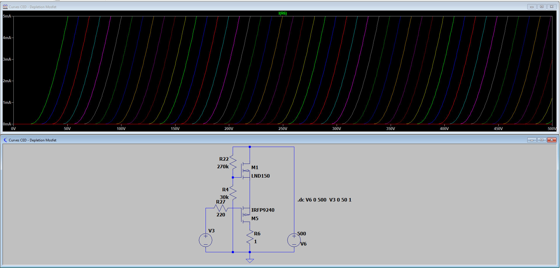
I don't want to hi-jack the thread, but I was thinking about a proper way to manage a SS recovery stage for a loop of an instrument amp, and I though of applying the same concept to a LND150. Curves seems very promising on LTSpice, I will try them in reality too.
What do you think?
Thanks in advance
I'd really appreciate if you would like to discuss about it, I've opened a dedicated thread citing you as reference: Triode-like curves from a n-channel DMOS (and not only)
Simulations are promising: 2Vrms at input give 110Vrms with a 0.015% of 2nd harmonic, everything else is in the ppm or subppm range:
Simulations are promising: 2Vrms at input give 110Vrms with a 0.015% of 2nd harmonic, everything else is in the ppm or subppm range:
Code:
Harmonic	Frequency	 Fourier 	Normalized	 Phase  	Normalized
 Number 	  [Hz]   	Component	 Component	[degree]	Phase [deg]
    1   	1.000e+03	1.544e+02	1.000e+00	    0.09°	    0.00°
    2   	2.000e+03	2.403e-02	1.556e-04	   89.36°	   89.27°
    3   	3.000e+03	1.085e-03	7.028e-06	   17.99°	   17.90°
    4   	4.000e+03	3.850e-04	2.493e-06	  143.15°	  143.06°
    5   	5.000e+03	2.118e-04	1.371e-06	 -166.45°	 -166.54°
    6   	6.000e+03	1.003e-04	6.495e-07	 -170.27°	 -170.36°
    7   	7.000e+03	9.481e-05	6.139e-07	  178.39°	  178.30°
    8   	8.000e+03	8.365e-05	5.416e-07	 -179.69°	 -179.78°
    9   	9.000e+03	7.412e-05	4.799e-07	  178.77°	  178.68°
Total Harmonic Distortion: 0.015577%(0.015555%)I'd really appreciate if you would like to discuss about it, I've opened a dedicated thread citing you as reference:
Please understand that I get more posts, email, and PM's that I can possibly answer. Many ask questions that I can not possibly answer like "how does a certain amp sound with a certain speaker?" When I have never seen either of them. Or "can you tell me which OPT to buy?" in a country where I can't possibly know what the options are.
Purely solid state circuits are not high on my list, as there are plenty of people here who are far better with solid state audio then me. Most of my solid state designs were at RF and my solid state audio DIY had waned by the mid 80's with clones of all the "Tigers."
In this post I see a somewhat typical mosfet cascode circuit with no clear labels as to input and output. I have been working with a similar circuit to drive a tube in CED mode without over stressing the Pmos fet.
In the circuits you posted in your two other threads I see the same circuit with another Nmos fet on top of it. You post some sim data showing good results. A successful sim only tells you that the concept has promise. It does not find all the possible pitfalls like blown mosfets due to undocumented SOA issues.
If I were doing this, and it interested me, this is the point where I would build it and see what it does in the real world. What happens after that would depend on the results. A positive result may get me back to the sim for some iterative tweaking. That's what happened with the UNSET design and it was nearly a year long process.
Sometimes I never return to the simulator, since it is just one of many tools in my arsenal, as is the soldering iron. There were many people where I worked who only worked in the simulator world. They were what kept me employed for 41 years. Someone somewhere must actually build something, since Motorola sold two way radios and phones, not pretty Powerpoint slides of simulations. I was the guy who built the prototypes, and it's still my preferred way of designing stuff.
At this moment I have two partially working amplifiers on my workbench, one being the current UNSET board. All of my Tubelab time is currently being spent on these. I can see some merit in what you have done, but I don't have the time to simulate or build it now.
I do have something similar on a breadboard with a tube in place of your top LND150. In fact there are two different "somethings." Where things go from here is yet to be determined.
- Home
- More Vendors...
- Tubelab
- UNSET is coming?