I see 5 board orders so far. They will all go out Monday. I'll start the parts list and construction notes tonight.
Tomorrow is my youngest grandkid's 7th birthday. No useful work will occur tomorrow unless you count the clean up operation.
Three weeks ago it was the oldest grandkid's 16th birthday. I got him a cell phone and built him a better PC. He was using my old Core II Quad box still running Vista. Now he has a 3rd gen Core i5 with W10. Its still far cheaper than a car.
For now, its back outside.
Thanks for shipping George,
I would like to try GU-50 on one of the two boards, so I've simulated GU50 curves with 10% (120k+150k a to g1, 33k g1 to gnd) and g2 at 180V, added the 44W (40W plate +10% pMosfet) max dissipation curve and the 4k loadline. I'll also raise g3 to +15V circa to sharpen the knee of the pentode.
Would you set B+ around 420V and something less than 100 mA at idle?
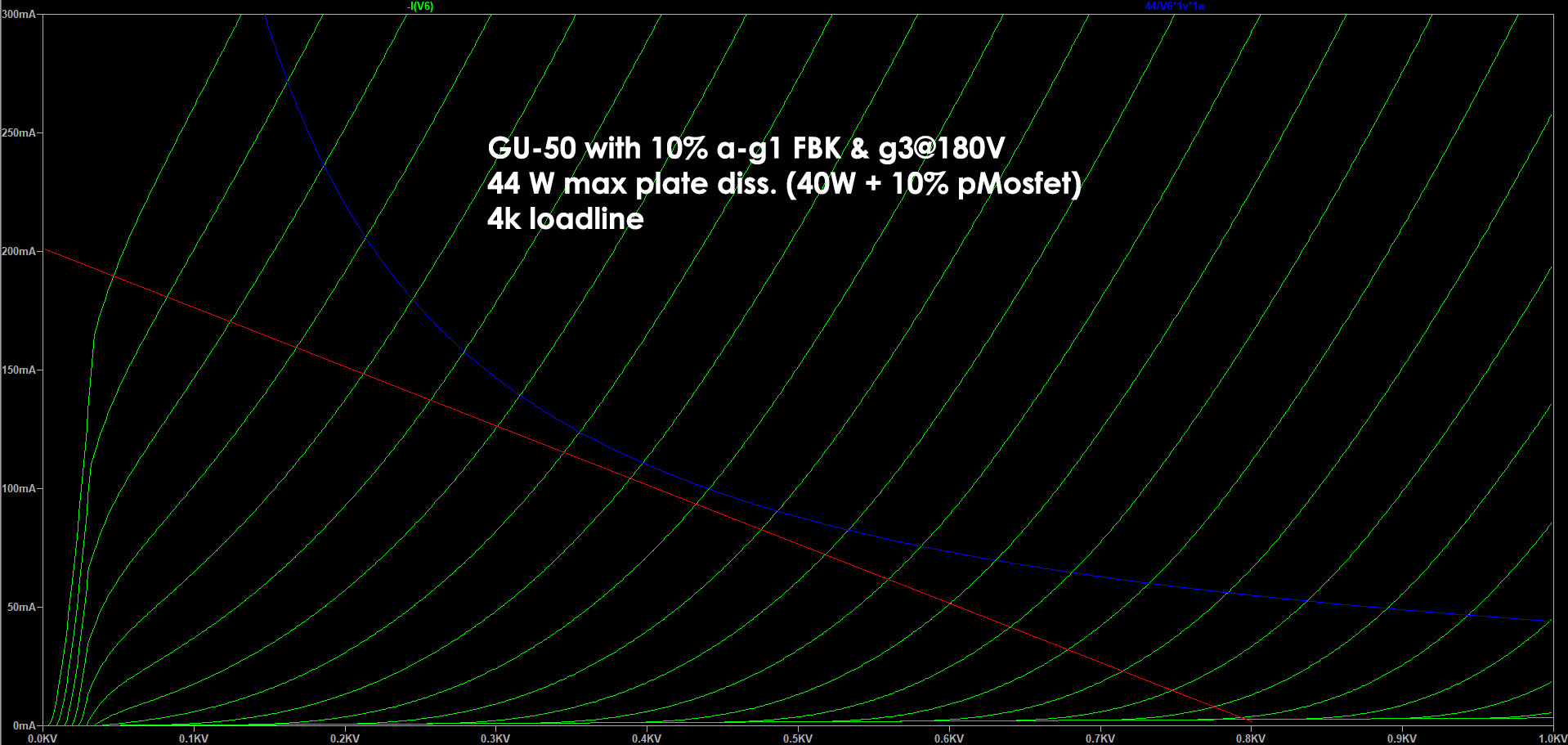
That would mean biasing around -45V, so a total swing of 90 + 80 (circa) so 170Vpp to reach full power, that will be around 17 Wrms.
Is it preferred to run it at lower voltages with higher g2 voltages and lower Ra?
If you prefer to switch all technical questions to another thread, it's perfectly fine for me.
I would like to try GU-50 on one of the two boards, so I've simulated GU50 curves with 10% (120k+150k a to g1, 33k g1 to gnd) and g2 at 180V, added the 44W (40W plate +10% pMosfet) max dissipation curve and the 4k loadline. I'll also raise g3 to +15V circa to sharpen the knee of the pentode.
Would you set B+ around 420V and something less than 100 mA at idle?
That would mean biasing around -45V, so a total swing of 90 + 80 (circa) so 170Vpp to reach full power, that will be around 17 Wrms.
Is it preferred to run it at lower voltages with higher g2 voltages and lower Ra?
If you prefer to switch all technical questions to another thread, it's perfectly fine for me.
Attachments
The post office says I have an UNSET board waiting in the mailbox at my office, but I'm ninety miles away for the next few days, at least.
There were a total of 7 orders for the beta UNSET boards, so at this time there are some left. A couple potential builders expressed concern about parts availability in a world that can't even build cars right now for lack of chips.
Fortunately the UNSET design does not contain any "chips" but it does contain semiconductors and some are in short supply. Here is a list of what's needed, why it was chosen, and some possible alternatives.
The board has a place for a rectifier tube socket. The usual tube rectifier in a build like this is a 5AR4, but it is only good to a bit over 200 mA at 400 to 450 volts, and that's with silicon diodes in series with each plate. If a 5AR4 is used D1 and D2 can be 1N4007's, UF4007's or any of the larger diodes are used for D1 and D2.
For higher powered operation the rectifier tube is bypassed and larger diodes are installed for D1 and D2. The BY228-15 is good for B+ voltages approaching 500 volts. It is cheap and available. The DSA1-18D is good to about 600 volts of B+, but they are pricey, about $5 each and hard to find. Digikey and Mouser do have them now, they did not last month. That's what's currently in my board.
The power supply uses an N-channel mosfet / zener circuit to derive the screen voltage from main B+. This means that 400+ volts can be dropped across the fet in a 600 volt amp. Ordinary mosfets that were designed for SMPS circuits will die the first time the amp is driven to hard clipping even if operated well within the published ratings. This is due to a secondary breakdown effect not well known in mosfets until about 5 years ago.
Some manufacturers still deny its existence and continue to publish DC SOA graphs that will lead to blown fets ON Semi / Fairchild are the worst case here. Any mosfet that does not explicitly state applications that require operation in the LINEAR REGION are not to be trusted. Some mosfets mention "audio amplifier" in the possible uses, but this could be a class D amp. Any mosfet that has a published SOA where no DC curve is also not suitable here. I have a good sized collection of blown fets created simply by plugging my guitar preamp into the UNSET board and setting the knobs on 10.
It is believed that all DEPLETION mode mosfets do not have this failure mode, and indeed so far I have not blown up a 3 amp 1000 volt depletion mode mosfet. It is the IXYS IXTP3N100D2. Unfortunately Digikey has none in stock and Mouser is down to 166 of them. The IXTP3N50D2 should also work in an amp that runs less than 500 volts of B+ but I have not actually tested them. Mouser has 99 of them. The IXTP1R6N50D2 Is in stock, and should also work, but again I have not tested them.
I have some of these fets on order along with a few others, which will all be tested on arrival. These fets are not available in an isolated package so an insulator will be needed to avoid having B+ on the heat sink.
The output stage needs a P-channel fet that will also spend it's life in the linear region. The mosfet of choice here is the ON / Fairchild FQPF9P25 (isolated) or FQP9P25 (non isolated). The tab on this fet operates at less than 1 volt, so an insulator would only been needed in a situation where the heat sink is grounded. Mouser and Digikey have them. The non isolated fet will do a better job of transferring it's heat to the heat sink, so they are a batter choice if the 1 volt or so on the heat sink is not a problem. I have also ordered some lower powered mosfets with lower capacitance for testing, but it is believed that they are not needed.
The small mosfets and zener diodes all seem to be available in the 10's of thousands, so they are not an issue.
Got back into town and found the board in my mailbox - looks good!
Time to see what I have in stock, what I need to order ... I know I have the big pFET's in stock. I have some nFET's that should ( may ) work, although they are of dubious origin ( Ali Express ). But at least I have a lot of them!
Time to see what I have in stock, what I need to order ... I know I have the big pFET's in stock. I have some nFET's that should ( may ) work, although they are of dubious origin ( Ali Express ). But at least I have a lot of them!
Last edited:
Digikey shipped my order yesterday by Fedex two day. Fedex is pretty unreliable here, so I may get them this week sometime.
The N-channel mosfet is the screen supply, and the positive cathode bias reference. When mosfets fail they usually fail to a short. This puts full B+ on the screen grid which should make a sweep tube blow, fry, or maybe explode.
After blowing several mosfets in am amp with 600 volts of B+, yet not hurting a single tube, I realized that the cathode was yanked to about +125 volts fully cutting off the tube.
Mosfets blow pretty easily in a 600 volt amp, but not so much in a 350 volt amp. I plan to do some more testing once my part arrive and I have more than one working board.
Best I recall, they are "supposed" to be 800 and 900 volt parts, but apparently I left them at the lake with several other unopened mailers of parts. I'm two or three orders behind on opening received parts orders ...
The board contains a 9 pin socket wired to accept any tube with the 9AQ, 9PM, 9NW, 9GK, 9BF, and 9AU pinout. Some type numbers are .... 6GK6 ....
I haven't been paying as close attention to this thread as I should have, I guess, but I've been going back through it to get a feel for the UNSET board and required parts and this caught my attention. Maybe I should not have given away my 4CX250 stuff?
To my untrained eye, these off shore PCB's look to be good quality. The layout around the power tubes looks very straightforward, and I understand the MOSFET flipping now that I have a board in hand.
I am leaning to building mine silk screen up as a breadboard to help understand and play with the circuit - it looks complicated.
Hot diggity dog - a case I thought would for sure go to trial Aug 2 looks to have settled, and my ordeal with the state of OK set for July 30 also looks it will be postponed, AGAIN, so that gives me time to do a quick wind down on the other thing and get back to tubes and parts with leads on them.
Last edited:
I am beginning to put my Mouser order together and will place the order as soon as George can provide the parts list.
Meanwhile, I have a question regarding George’s recommendation of the DSA1-18D high voltage rectifier diodes. Are they preferable over the Wolfspeed SiC Schottky diodes such as C5D05170H which could be had for a similar price from Mouser, and if so why? Granted the Vrrm is respectively 1.8 and 1.7kV, but either should be fine for a B+ of 600V, I think.
Meanwhile, I have a question regarding George’s recommendation of the DSA1-18D high voltage rectifier diodes. Are they preferable over the Wolfspeed SiC Schottky diodes such as C5D05170H which could be had for a similar price from Mouser, and if so why? Granted the Vrrm is respectively 1.8 and 1.7kV, but either should be fine for a B+ of 600V, I think.
The post office says I have an UNSET board waiting in the mailbox at my office, but I'm ninety miles away for the next few days, at least.
Finally the request to pay the import duties arrived after which the post service can plan delivery.
It's just that right now I'm 10000km (6200 miles) away.
Now they will have to wait.
But it's surely something to look forward to for when I get back 😎
I've receipt them yesterday.
I've one question: planning to use GU-50 on one board, I would like to give +15V on g3. Is there a simpler way than having two floating power supplies?
I've one question: planning to use GU-50 on one board, I would like to give +15V on g3. Is there a simpler way than having two floating power supplies?
I have a question regarding George’s recommendation of the DSA1-18D high voltage rectifier diodes. Are they preferable over the Wolfspeed SiC Schottky diodes such as C5D05170H
I have never tried the Wolfspeed or any SiC diodes, so I don't know for sure how they would work. I imagine that they would be fine if they physically fit in the board.
We live out in the country where our power is not too reliable. My amp was playing one day when the power started going off and on several times before going off for nearly a day. That is often death to a tube amp, but it and the DSA1's were fine.
I had 3 working boards at one time, the two original home cooked prototype boards, and one of the commercially made boards like you have. The first prototype board was robbed of several parts for boards #4 and 5 including the heat sinks which did not come out cleanly. The second prototype has been used for nearly continuous listening for several months. It has seen minimal changes or testing due to its DIY board's rather sketchy quality and lack of through plated holes.
I have spent much of the last week testing all the parts that I got from Digikey and Mouser in the board to verify that they will work and fit properly. The 4th board is currently being used to verify pars fitment in a pars on the bottom side build. All electrical testing has occurred at B+ voltage levels just under 400 volts to just over 500 volts because that's where I think most boards will be used.
At this time I wouldn't run the board at 600 volts unless you could provide a separate screen supply and a good scheme for heat sinking the mosfets.
My boards use 500 volt caps, and that's what's going into the parts list. Electrolytics for over 500 volts are hard to find, and few builder will use them so I have not done much recent testing beyond 520 volts (as far as I dare to push 500 volt caps). I have run my board to 630 volts on an external power supply with it's 500 volt caps removed, so I know that the design is capable of going that far, but forced air was needed. I plan to make some high powered push pull amps with the UNSET tech, but that's probably best left to the modular design that many users want.
I tweaked a few resistor and cap values, and once I get the parts list to match what's in my boards and verify fitment of all parts the parts list will go in another thread, the UNSET board build thread.
In other news, I did manage to blow up one of my boards twice today. Once was due to a slipped screwdriver on a live board. The second time it blew I was just playing music from a phone at a loud level with some periodic clipping seen on the scope. The plug into my phone was intermittent and it came out when I picked it up to change tracks. Plugging the cord back into the phone at full volume managed to blow the screen regulator mosfet, which seems to be the weakest link in this whole amp. I was running about 20 watts into 4 ohm speakers on 520 volts when it happened. I installed the bigger $5 fet set the power supply on 450 volts cranked it up to full tilt and repeatedly plugged and unplugged the phone jack without issue. I did not repeat the test at 520 volts though. I decided to add some resistance in series with the screen grids first. I may get to try that tomorrow.
Big sound needs big tubes and transformers.
Attachments
Thanks for the nice update. It is great to hear of your progress, explorations and especially the blow-ups on our behalfs. Looking forward to the new thread for UNSET PCB building when you are ready for it.
The Wolfspeed SiC Schottky C5D05170H comes in a TO-247-2 package and has 0.4 inch spacing for the solder pins. I assume the current test PCB design has a 7.5 mm spacing needed for DSA1-18D (I am still away from home and have not seen the PCB). Perhaps the final UNSET PCB could provide an extra hole to accommodate either diode. I plan to use the Wolfspeed part in my build of the test PCB, since I have some, and will drill a hole as needed. When all said and done I shall comment on this SiC diode in the UNSET.
The Wolfspeed SiC Schottky C5D05170H comes in a TO-247-2 package and has 0.4 inch spacing for the solder pins. I assume the current test PCB design has a 7.5 mm spacing needed for DSA1-18D (I am still away from home and have not seen the PCB). Perhaps the final UNSET PCB could provide an extra hole to accommodate either diode. I plan to use the Wolfspeed part in my build of the test PCB, since I have some, and will drill a hole as needed. When all said and done I shall comment on this SiC diode in the UNSET.
Sometimes it's the simplest of things.....
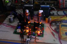
I have several UNSET boards in various states of build completion, but two that see most of my testing duties.
One is the second prototype still on a DIY PC board, called the brown board. It has been used for daily listening for months with a wide variety of music, volume levels, and at least 4 different sets of speakers. It has just worked, flawlessly.
The other is a newly constructed test board on the first of the new production PC boards. It is the green board. In a hurry to build it, I canabalized the original first prototype board for parts destroying it in the process. It has worked well....until a few days ago when I blew up a mosfet.....then another.....
My test setup is not exactly the neatest in the world, but it has worked for me on everything from tiny 4 watt guitar amps to an UNSET board driven to 250+ watts in push pull for the past 6 years.
In many tests I use a pine "breadboard" with a pair of my Universal Driver boards on it and swappable output tube boards, but here everything is just connected up on a cardboard box to avoid unnecessary benchtop wear. My particle board benchtop in Florida began to come apart after about 15 years and eventually failed after about 20. This one is covered in hardwood laminate flooring "samples" obtained from a defunct carpet shop.
There are two 500 watt 8 ohm resistors behind the OPT's. I bought them after a previous dummy load went open at 160+ watts setting an OPT on fire. You can see a mess of clip leads connecting the audio analyzer and scope to the resistors. Two sets of speaker wires (blue and gold) are also connected as needed with clip leads.
The inputs are wired directly to a dual 10K pot with RCA jacks soldered directly to it. Phones, iPad, CD and DVD players are connected with the appropriate interconnect cable, the audio generator is connected with clip leads.
Despite this mess I can measure THD's down into the 0.2% range on this board at low power levels, where the generator directly to the analyzer reads 0.1%. It's good enough for tube amps.
I have seen the green board blow up several times in the past 4 days. It can be just cranking some music and the slightest disturbance causes a mosfet to blow, often splitting the plastic. I even blew one of the cathode drive mosfets. These occur quickly without warning, so I have never been able to catch anything on a scope. I even had as many as 6 multimeters wired into the board trying to figure out what causes the failure. Each failure involved some action by me. I was near, or touching the board when it went bang. If I was across the room listening, it never blew. All testing was done using an external power supply for B+ to evaluate things at various B+ settings without swapping power transformers. I could run the board at the limit of my power supply (300 mA) and even bury the needle on it's current meter without blowing anything, then watch it blow at 200 mA total on 460 volts.
Could it be a loose connection? Why did my brown board never blow, even at 600 volts?
All but one failure involved just the screen supply mosfet. The BIG bang blew a screen supply fet AND a cathode drive fet. What's making the screen fet blow?
I was about to swap in my brown board when I decided to run the green board from an external screen grid power supply. I connected up my Knight Kit power supply to the screen grid of the output tubes, and cranked up the board. Everything appeared to be normal so I started playing with the plug on the phone. Both current meters pegged and the scope lit up with 40 volt P-P distorted sine waves at 44 KHz. The screen current was over 300 mA for two tubes, of course the fet blew. It was eating 100 watts or more. An open circuit caused no issue, but touching the input brought both a distorted 60 Hz buzz, some random high powered oscillation at 35 to 45 KHz, and a whole lot of tube current. That big Hammond OPT is nearly a dead short at those frequencies (OPT's are highly capacitive beyond their resonant notch).
My first thought was, "Why didn't I see this on my other board?" So, I decided to swap it into the setup. That's when it all became obvious.
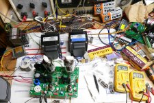
If you look in the picture you will see a long black clip lead, one of three connected to an easy to get ground point on the front of the board, running around the left side of the board behind the roll of solder to the load resistors. It provides a ground connection for the OPT secondaries, the speakers, and all the test equipment connected to the amp output.
That clip lead was still attached to the brown board which was up on a shelf out of sight, and therefore missing from the test setup. Replacing the clip lead made all the evil mosfet eating oscillation go away. The amp has been tested at 520 volts with the bare input, me touching it, and even poking it at random metal objects with nothing more than clicks and buzzes (normal).
Now some more "normal" testing can resume.
I have several UNSET boards in various states of build completion, but two that see most of my testing duties.
One is the second prototype still on a DIY PC board, called the brown board. It has been used for daily listening for months with a wide variety of music, volume levels, and at least 4 different sets of speakers. It has just worked, flawlessly.
The other is a newly constructed test board on the first of the new production PC boards. It is the green board. In a hurry to build it, I canabalized the original first prototype board for parts destroying it in the process. It has worked well....until a few days ago when I blew up a mosfet.....then another.....
My test setup is not exactly the neatest in the world, but it has worked for me on everything from tiny 4 watt guitar amps to an UNSET board driven to 250+ watts in push pull for the past 6 years.
In many tests I use a pine "breadboard" with a pair of my Universal Driver boards on it and swappable output tube boards, but here everything is just connected up on a cardboard box to avoid unnecessary benchtop wear. My particle board benchtop in Florida began to come apart after about 15 years and eventually failed after about 20. This one is covered in hardwood laminate flooring "samples" obtained from a defunct carpet shop.
There are two 500 watt 8 ohm resistors behind the OPT's. I bought them after a previous dummy load went open at 160+ watts setting an OPT on fire. You can see a mess of clip leads connecting the audio analyzer and scope to the resistors. Two sets of speaker wires (blue and gold) are also connected as needed with clip leads.
The inputs are wired directly to a dual 10K pot with RCA jacks soldered directly to it. Phones, iPad, CD and DVD players are connected with the appropriate interconnect cable, the audio generator is connected with clip leads.
Despite this mess I can measure THD's down into the 0.2% range on this board at low power levels, where the generator directly to the analyzer reads 0.1%. It's good enough for tube amps.
I have seen the green board blow up several times in the past 4 days. It can be just cranking some music and the slightest disturbance causes a mosfet to blow, often splitting the plastic. I even blew one of the cathode drive mosfets. These occur quickly without warning, so I have never been able to catch anything on a scope. I even had as many as 6 multimeters wired into the board trying to figure out what causes the failure. Each failure involved some action by me. I was near, or touching the board when it went bang. If I was across the room listening, it never blew. All testing was done using an external power supply for B+ to evaluate things at various B+ settings without swapping power transformers. I could run the board at the limit of my power supply (300 mA) and even bury the needle on it's current meter without blowing anything, then watch it blow at 200 mA total on 460 volts.
Could it be a loose connection? Why did my brown board never blow, even at 600 volts?
All but one failure involved just the screen supply mosfet. The BIG bang blew a screen supply fet AND a cathode drive fet. What's making the screen fet blow?
I was about to swap in my brown board when I decided to run the green board from an external screen grid power supply. I connected up my Knight Kit power supply to the screen grid of the output tubes, and cranked up the board. Everything appeared to be normal so I started playing with the plug on the phone. Both current meters pegged and the scope lit up with 40 volt P-P distorted sine waves at 44 KHz. The screen current was over 300 mA for two tubes, of course the fet blew. It was eating 100 watts or more. An open circuit caused no issue, but touching the input brought both a distorted 60 Hz buzz, some random high powered oscillation at 35 to 45 KHz, and a whole lot of tube current. That big Hammond OPT is nearly a dead short at those frequencies (OPT's are highly capacitive beyond their resonant notch).
My first thought was, "Why didn't I see this on my other board?" So, I decided to swap it into the setup. That's when it all became obvious.
If you look in the picture you will see a long black clip lead, one of three connected to an easy to get ground point on the front of the board, running around the left side of the board behind the roll of solder to the load resistors. It provides a ground connection for the OPT secondaries, the speakers, and all the test equipment connected to the amp output.
That clip lead was still attached to the brown board which was up on a shelf out of sight, and therefore missing from the test setup. Replacing the clip lead made all the evil mosfet eating oscillation go away. The amp has been tested at 520 volts with the bare input, me touching it, and even poking it at random metal objects with nothing more than clicks and buzzes (normal).
Now some more "normal" testing can resume.
Attachments
Last edited:
Fantastic! Slayed one more of those mystery bugs! Good to know the test (green) boards seem to work well. Good luck with the “normal testing” and completion of the parts list.
I went ahead and bought some of the SS devices used for UNSET that have limited inventories at Mouser. In looking around (I also ordered parts for the SPP EL86 build) at electrolytic capacitors, WW resistors, etc., I was alarmed at what appears to be an inventory crisis. Many of these parts have zero stocks and long lead times.
I went ahead and bought some of the SS devices used for UNSET that have limited inventories at Mouser. In looking around (I also ordered parts for the SPP EL86 build) at electrolytic capacitors, WW resistors, etc., I was alarmed at what appears to be an inventory crisis. Many of these parts have zero stocks and long lead times.
Last edited:
...
I went ahead and bought some of the SS devices used for UNSET that have limited inventories at Mouser...
I did the same. The electronic parts industry is all upside down right now 😕 Once George publishes his parts list I anticipate some difficulty in finding all the normally easy to source parts.
I am trying to pick parts that are in stock at both Digikey and Mouser. That is not always possible.
Is BSS84 still the designated little pFET?
Mouser only has it in smd packages. I'm okay with that, but it seemed odd.
George, the dubious big nFET's I have are marked FQPF8N80C. Who knows what they really are. I'm planning on starting out with low power / relatively low voltage, so we'll see if the scatter.
Mouser only has it in smd packages. I'm okay with that, but it seemed odd.
George, the dubious big nFET's I have are marked FQPF8N80C. Who knows what they really are. I'm planning on starting out with low power / relatively low voltage, so we'll see if the scatter.
Back in post #75 George mentioned that the actual part he used is Microchip VP0106. Mouser has over 1200 in stock right now.
Watching this thread with intense interest! Nobody knows how to squeeze the last ounce of performance out of a tube like George.
Good to see these glitches being ironed out. I debated whether or not to order one of the boards from the initial run, but decided against it as my time for experimentation is extremely limited. Better to save it for the inevitable troubleshooting, testing and measurements.
Good to see these glitches being ironed out. I debated whether or not to order one of the boards from the initial run, but decided against it as my time for experimentation is extremely limited. Better to save it for the inevitable troubleshooting, testing and measurements.
- Home
- More Vendors...
- Tubelab
- UNSET is coming?