take out the CMC and re-evaluate the schematic.If I do this, then I effectively short R5, R6 and the half of each CMC. I think the first cap zero volt and the final cap zero volt need to be separate, as are they really both at zero volts?
Then add the CMC and see what improvements it offers and whether the wiring that suited without CMC still gives better performance.
Finally, assess whether the wiring has to be modified to better suit the CMC improvements. On this last point I cannot offer any experience.
take out the CMC and re-evaluate the schematic.
Then add the CMC and see what improvements it offers and whether the wiring that suited without CMC still gives better performance.
Finally, assess whether the wiring has to be modified to better suit the CMC improvements. On this last point I cannot offer any experience.
right, so perhaps adding a jumper between the final cap and the first smooth cap would give the user the ability to experiment with four configs:
CRC CLC CLRC and C(CMC)RC
In the first three configs, yes the output ground would be connected to a star at the first smoothing cap. In the last config, it would be left floating. In either case, move the ground loop breaker to the output. The downside being, there could perhaps be a compromise by offering more than one connection. This is something I'm willing to accept for the flexibility of experimenting and learning.
Thanks again! All that's left is to help choose the CMC or L for the latter half of the circuit. That seems to be the rub...
I'll leave this an open question and begin specifying parts and patterns for the rest of the circuit and perhaps someone will pipe in later 🙂
luvdunhill -
Interesting thread...
Are you planning (or, at least, hoping) this progresses into a commercial board??? Or, a GB???
Interesting thread...
Are you planning (or, at least, hoping) this progresses into a commercial board??? Or, a GB???
any further updates or movement on PCB's?
yup, I've decided on the final parts (and have them in hand for prototyping) and have most of the non-standard parts designed in my CAD software... depending on how busy my work week is, I could have something for people to look at on Sunday or so.
excellent, more stuff to add to my power supply fetish, this your borbely boards and a design Natonrice is putting together should do me for quite a while. will keep an eye on this for the PCB
so, I've changed scope a bit. It doesn't take a complete layout to tell this is going to be way longer than I would like. So, I'm splitting it in half and the two sections will be stackable (or not). Also, adding a IEC PCB mount inlet option as well as making the entire thing compatible with a 75mm x 160mm Hammond case. The split will be right after the secondary RC snubber. This will also simplify all the jumpers after the secondaries, as these will now just be wires to the second board. Anyways, this is the plan. I need to rework some things now to make this happen...
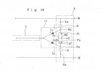
Researching for a similar dual PSU schematic I found a 1985 Patent by onkyo:
They invented a smoothing circuit between the transformer's center tab and the rail where the smoothing caps are tied together. This circuit is made from two antiparallel diodes D1 and D2 (aka D3 and D4 in luvdunhill's schematic).
Furthermore they suggest an improvement where the diodes are tied in a triangle.
I've never seen a schematic that include this simple device. Does it make sence? What type of diodes are the best for this job? Luvdunhill uses UF4007 - a good choice?
Attachments
The pdf-file cannot be opened...
Here is the link to US Patent 4,555,751:
Rectified and smoothed DC supplying circuitry - Patent 4555751
Here is the link to US Patent 4,555,751:
Rectified and smoothed DC supplying circuitry - Patent 4555751
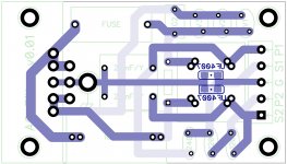
Well, it turns out that to fit this project where I want it to go, I have to separate the boards.
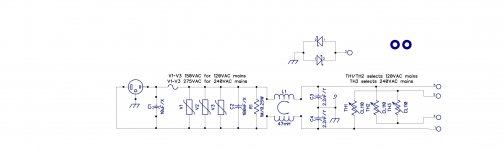
So, here's the AC input filter. Any suggestions? What about the location of the ground loop breaker (under the choke, and output "between" the transformer output)?
Thanks!
So, here's the AC input filter. Any suggestions? What about the location of the ground loop breaker (under the choke, and output "between" the transformer output)?
Thanks!
Attachments
Lol - I hadn't seen the original thread - this is how just about all my projects go, in 5 month increments as time permits. 🙂 Looks like a useful PCB. I would probably be in if there is a GB.
In addition to L-N MOVs you might consider N-G and L-G MOVs to nail common mode spikes.
In addition to L-N MOVs you might consider N-G and L-G MOVs to nail common mode spikes.
Last edited:
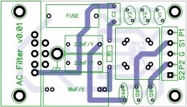
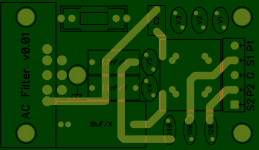
cool. I snuck them in after the fuse, to earth (not ground). Had to move R1 under the board, but it's not the end of the world... I'll probably make up a few at this point.
Attachments
Last edited:
- Status
- Not open for further replies.
- Home
- Amplifiers
- Power Supplies
- Unregulated Power PCB