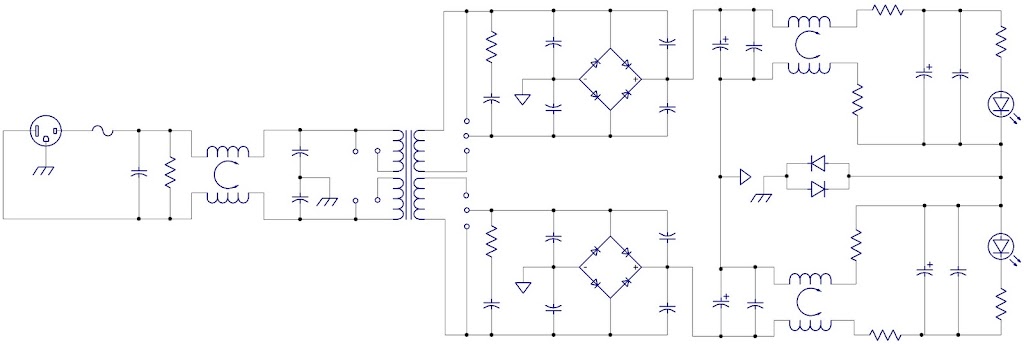
I have a few uses for a simple PCB that supports a number of different ~25VA PCB mount transformers with a bit of filtering on each side of the transformer. I'm trying to nail down the schematic a bit and wanted to see if there was any advice out there 🙂 Improvements perhaps?
I would allow for a thermistor like a CL60 on the input of the transformer.
Jim
Jim, I could do that, but we're dealing with probably a max of 25VA here. What value would be appropriate in this case? Seems like it wouldn't be much of an issue?
Hi,
How about adding lots of MOVs or similar across the L to N to limit the voltage spikes from the mains?
Allow for R+C across the diodes. some diodes do not need snubbers, other do need snubbers. Some misbehave badly when a single cap is paralleled across the diode.
Nothing wrong with dual rectifier. Rectifying each secondary and connecting them in series after the first stage smoothing is recommended by many.
Move the Safety Earth/Chassis connection from the output end of the PSU to the common point between the first stage smoothing caps. Join this zero volts point to the PSU output.
Send the PSU output to the main audio ground.
Thanks for the help, first of all!
A few comments:
I've never used a MOV, but the theory seems the same as a thermistor? Would it be possible to incorporate two of the suggestions and put one CL60 thermistor between the secondaries for 240V operation and use two for 120V? Around 10 ohms I'd assume would be fine? If I've assumed incorrectly, and a MOV behaves differently, any recommended part?
I understand moving the ground loop breaker to the first stage smoothing cap, good catch. However, if I connect this zero volt point to the output, I've effectively shorted one of the chokes, and ruining the idea of using a common mode device. Comments?
Finally, in hunting for these common mode devices, some don't list inductance at all in the datasheets, but impedance at a given frequency, DCR and a rated current. Some investigation says not much inductance is really required. I'm looking at this device at the moment and was wondering what you guys think:
http://www.steward.com/web_info/CADPrints/Sales/CM2545X171B-10-C-2.pdf
It's one of the rare, relatively compact through hole devices... my question is, perhaps I should be looking at a higher impedance device, in the order of 4-5 times larger?
MOV metal oxide varistor.
Varistor - Wikipedia, the free encyclopedia
It avalanches when the voltage exceeds it's rating, passing enormous current for a very short time.
Quite different from a Thermistor.
Varistor - Wikipedia, the free encyclopedia
It avalanches when the voltage exceeds it's rating, passing enormous current for a very short time.
Quite different from a Thermistor.
Hi,
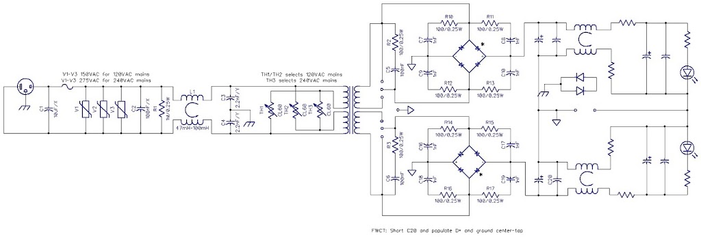
almost, but the wrong voltage rating.
In the UK we use 275Vac, chosen to exceed our maximum of 254Vac on our 240Vac nominal supply.
I would expect there to be 130/135/140Vac suitable for your lower voltage supply.
John Curl recommends a 10uF cap across the L&N at the distribution board to help with this spike and harmonic attenuation.
Nothing wrong with dual rectifier. Rectifying each secondary and connecting them in series after the first stage smoothing is recommended by many.
None of whom are engineers. So you like superstition?
Two FWBs means double the conduction loss, and you're already using double conduction loss as it is (relative to FWCT, but that requires more iron). There is absolutely no physical advantage to using two.
Tim
when building a monoblock, I agree, a single bridge rectifier from a centre tapped transformer is good enough. I cannot measurably improve on that.None of whom are engineers. So you like superstition?
Two FWBs means double the conduction loss, and you're already using double conduction loss as it is (relative to FWCT, but that requires more iron). There is absolutely no physical advantage to using two.
Tim
But other experts here say otherwise.
I will not hide all other opinions behind a smokescreen to try and confuse the beginners.
John Curl recommends a 10uF cap across the L&N at the distribution board to help with this spike and harmonic attenuation.
by distribution board, you mean right at the beginning of the PCB? I would think this location would be where the MOV would need to be placed to be effective.
Any comments on "floating" the connection after the CMC on the outputs from the ground point at the first cap after the rectifier (my post on Yesterday 02:28 PM)?
Also, what about the CMC part I posted in the same post, should I consider a larger impedance value? I think the board will also support two separate inductors, as well as a single inductor on the + line (in which case the output will be connected to the first cap). New schematic will be forthcoming, with a few values and notes included.
I think I can support the CT secondary with FWB using the jumper scheme you'll notice on the schematic right after the transformer and only populating one section. I'll have to sit down and think about it, but it should be sufficient.
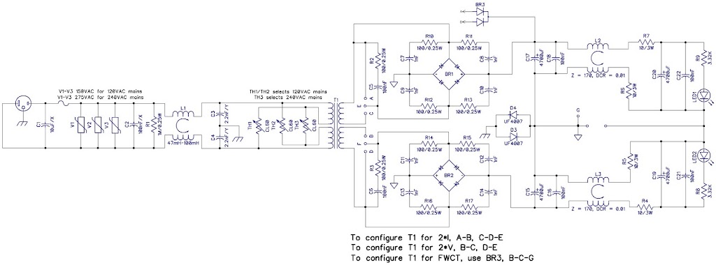
I think the ground loop breaker needs to be moved back to the output. With the CLRC filter it just doesn't make sense to ever connect the output to the first cap like AndrewT suggested. Perhaps he didn't read the schematic correctly, as these two points will never be at the same potential.. So expect that change tomorrow plus any suggestions that are made while I'm asleep tonite 🙂
you almost have it right.
Just a couple of mods for you to consider and then make a judgment on whether it is better or worse than your first.
Keep the Safety Earth to Zero Volts connection where it is.
Delete the G and ground triangle from the first capacitor junction.
Re-insert the G and ground triangle on the spare terminal that is adjacent to where you removed them.
Connect the first caps zero volts to the final cap zero volts (way over at the far right).
I am not sure how this affects the Centre Tapped option. But I am fairly sure it is OK for the Dual secondary and dual Bridge Rectifier option.
The Ground Loop Breaker, or Disconnecting Network as I have previously called it, is not needed for any Audio reason.
All audio equipment will amplify and/or play without the Safety Earth connection.
The Safety Earth connection is only needed for SAFETY reasons. This connection will make the Audio performance worse.
Now what does the Safety Earth connection need to consist of, to ensure it meets it's SAFETY purpose.
It can be a direct wire connection capable of passing kA without failing while the mains fuse ruptures and the arc extinguishes.
or
It can be a Network of components that can pass kA without failing while the mains fuse ruptures and the arc extinguishes.
Can you guarantee that your uf4007 comply?
Now look at the audio necessities.
The charging pulses between the transformer and the rectifiers and the first stage smoothing caps must be kept in a short tight (low loop area) circuit.
That circuit must not share any wire with another circuit.
If necessary delete all components and wiring that are not in this charging circuit and draw out what is needed for that circuit to work (as a circuit). Look at it and determine where the charging current flows. In what direction the current flows during each half mains cycle. Now consider the actual voltage drops along all the wires or through all the components in that charging circuit.
Apply real voltage values if need be to see the effect that the current pulses will have on the voltages around the charging circuit.
Now add on the second stage smoothing. consider the circuit feeding the amplifier. Are any wires sharing currents from the clean(ish) feed to the amplifier and the dirty circuit back to the transformer.
If there are any that share dirty current with cleanish current then you need to rewire your added clean smoothing side until you eliminate all shared current paths.
Last edited:
Connect the first caps zero volts to the final cap zero volts (way over at the far right)
If I do this, then I effectively short R5, R6 and the half of each CMC. I think the first cap zero volt and the final cap zero volt need to be separate, as are they really both at zero volts?
- Status
- Not open for further replies.
- Home
- Amplifiers
- Power Supplies
- Unregulated Power PCB