IAIMH,
Go with LT4320 active rectification. Excellent for Class A amps and no need to be so concerned about snubbers.😉
Go with LT4320 active rectification. Excellent for Class A amps and no need to be so concerned about snubbers.😉
^ Ugh... you're killin' me, Smalls! 🙂
I considered it. I have several of Prasi's boards... both TH and SMD... but ... I think ... I'd have to double them up to get to my 50V target ... wouldn't I? Used them for the Singing Bush supply. I shamelessly copied Botte's work.
Edited to add - Prasi's boards also have provisions for snubbers... but I never know when they're needed or not... I assume, but I'm not sure... if you're saying that I don't have to worry about snubbers for the rectifiers vs. the transformer ringing?
Edited upon edited to add - If I need to double them... even though cost seems to be no object in this, I need to keep a bit of a rein on it... I think I'd need 8 boards / sets of devices. If that's the case, I don't have enough parts / boards... and unless there's a compelling reason, I'd avoid that extra cost over things I have on hand.
Still, I welcome thoughts around that concept.
Last edited:
I was just in the middle of typing about the AR solution. I switched over to the LT4320's for my amps ~1 year ago. No complaints yet. If I had to give a rough guess, I'm probably getting ~5% better efficiency with those. Went from legacy bridge / MOSFET cap multiplier to an AR / CLC and rails went from 22.7V to 28V, still very low noise....
Attachments

Yup, no more legacy bridge rectifiers for me either.
IAIMH, not sure what you mean about “doubling up”? LT4320 is good for 70VDC output.
IAIMH, not sure what you mean about “doubling up”? LT4320 is good for 70VDC output.
^ Hmmmmmm.... Then I need to do more reading and understanding.... or check my specific parts and boards.
I had it stuck in my head when using them for the Singing Bush (single rail +63V, I think) that the reason I needed to use two in series along with the arrangement chosen was because of the voltage rating for the parts.
I completely misinterpreted and/or missed something... I also have 4 of them right in front of me...
More to do...
Thanks!!!!
It you have 4 ideal bridges, that will be perfect for a dual mono bipolar power supply. What are you waiting for, get rollin’ 
@william2001 and @Vunce -
Thank you! I still want to do a bit more reading to see where I've completely misinterpreted something... lay out a wiring diagram, and get some additional thoughts. I've only used them once, and it was in the sincerest form of flattery (a direct copy with permission) of someone else's work.
Before I venture off beyond the fences, I want to do a bit more homework. It's not second guessing you guys at all, but to figure out why I thought what I thought and make certain that I understand it.
Dag-nab it... now I wish I had decided to put 80V caps in this PSU... then I could have used this for Singing Bush... I still have those cap banks / filter networks, and Randy modded them for easier CLC use ...
hmmmmm
OK - quiet reading time...
hmmmmm
OK - quiet reading time...
Well, fortunately ... or unfortunately ... I keep really detailed notes.
From an e-mail... discussing why in a specific case, two were used in series. I hope @Botte doesn't mind a bit of additional public praise and thanks. He patiently, very, very patiently, explained a great deal of his process to me in 2020...
Me: "You mentioned a 70VDC limit, were you trying to be conservatively under that?"
Botte: "Yes"
Me: "I looked at the specs, and I couldn’t quite wrap my head around it."
Well, some things don't change. I'm getting better. Sloooooooowly.
Looks like we're going with those. I have the parts and boards, and they by all accounts seem to be 'better'.
Thanks to all!
More to come... Now I need to find everything and re-do a layout.
AC line voltage fluctuations at my home, summer to winter, could have put me close to max. I always try to derate by at least 25%. So I sleep better at night. I was changing from a pos-neg supply to just a single higher voltage. So I just jumped them.

Then... there is this lone tidbit... from Elliott's work.
There is one application where fast diodes are definitely recommended, and that's for 'choke input' filters, where the diodes feed rectified AC to the filter cap(s) via an inductor. These are not covered here because they are extremely uncommon in modern equipment, although a superficially similar arrangement is often used in regulated switchmode power supplies.
I will be using a chokes as part of the filtering...
Note that he was referring to "choke input" filters which are LC filters, that is, the choke is connected directly to the rectifiers. It is a different situation when it is CLC, especially when the Cs are large.
People have expressed both positives and negatives for chokes in power supplies. In my opinion, the positives outweigh any negatives if you have highly sensitive speakers as the huge power supply ripple reduction due to a CLC filtering is audible due to its lack of noise, whereas a CRC filter with the same amount of C may have audible noise.
I have highly sensitive speakers and I have mostly Class A single ended amplifiers, which are noisier than push-pull amplifiers, so I have CLC filters in all of my amplifiers. I have Quasimodo determined snubbers after standard monolithic bridge rectifiers, and no resistors either in parallel or series with the chokes. I hear no noise at all from my 103dB speakers and I am very happy with the sound.
So as Zen Mod in the CLC thread, try it "in vivo". There are theories and simulations but try it in real life and decide for yourself what is important to you. That is the beauty of DIY - you can experiment and determine what is best for you. 🙂
Zen Mod's take on PS chokes
Thank you for the added information, Ben. I had never seen a choke directly after the rectifiers, so I incorrectly assumed that it would be part of a CLC or similar. Your thoughts, along with everyone including the Zen Master's himself are very much appreciated. I had read that thread over and over. The measurements were confidence inspiring. There's one person that has recommended against chokes in PSUs with regard to their perceived affect on sound quality. I trust their opinion ... so I'll be able to swap them in and out. 🙂 I'm starting with them in.
I embrace trying various things. I've been fortunate to build my fair share of amps, and I'll be building a lot more. 🙂 I've been reluctant re: PSUs, b/c anything touching mains always gives me additional pause. Even though I try to be very, very thorough, I don't have the confidence that comes from knowledge. Everything thus far has been following the build guide for the 4 identical First Watt style supplies or mimicking Botte's work directly for the Singing Bush.
Within this implementation, things should be easy(ish) to swap out. If I want to remove the chokes and try resistors in place... sure. If I can finally get parts for Tombo's cool solution ... I can go for it. If I need higher voltage, I can swap cap banks / filters up to a reasonable limit for the LT4320. If I need to go higher, I can run them in series like Botte did. Mix and match as needed. That's the idea anyway. Anand's @poseidonsvoice amplifier test bed was one of my many inspirations. I'd like to swap things in and out with confidence and be able to attach most of the amplifiers I see in my future. There will always be exceptions... but ... it's the idea.
I've got to decide, or I'll suffer from analysis paralysis. For now... the first iteration, I'm sticking with the following building blocks...
Unregulated PSU. Regulated has its supporters, and I'm not done thinking about it... but for now... unregulated.
Just got my delivery from ModuShop... 🙂 So... this is roughly what it may be on the floor plan... I have a bit more room to work... the floor is bigger b/c of no heatsinks to take up width.
I embrace trying various things. I've been fortunate to build my fair share of amps, and I'll be building a lot more. 🙂 I've been reluctant re: PSUs, b/c anything touching mains always gives me additional pause. Even though I try to be very, very thorough, I don't have the confidence that comes from knowledge. Everything thus far has been following the build guide for the 4 identical First Watt style supplies or mimicking Botte's work directly for the Singing Bush.
Within this implementation, things should be easy(ish) to swap out. If I want to remove the chokes and try resistors in place... sure. If I can finally get parts for Tombo's cool solution ... I can go for it. If I need higher voltage, I can swap cap banks / filters up to a reasonable limit for the LT4320. If I need to go higher, I can run them in series like Botte did. Mix and match as needed. That's the idea anyway. Anand's @poseidonsvoice amplifier test bed was one of my many inspirations. I'd like to swap things in and out with confidence and be able to attach most of the amplifiers I see in my future. There will always be exceptions... but ... it's the idea.
I've got to decide, or I'll suffer from analysis paralysis. For now... the first iteration, I'm sticking with the following building blocks...
Unregulated PSU. Regulated has its supporters, and I'm not done thinking about it... but for now... unregulated.
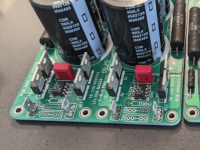
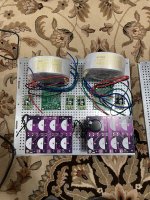
- LT4320 'ideal' rectification with Prasi's boards. They have placement for snubbers, but I am not sure how to best implement snubbers b/c I will be swapping transformers as needed. Thanks to the most recent advice, I'm heading this way.
- CCLCRC filtering with the V8 boards and chokes.
- 66kuF (2x33kuF) 50V
- Hammond 159ZJ 10mH @ 5A - 0R160 series resistance
- 33kuF
- 0R165
- 33kuF
Just got my delivery from ModuShop... 🙂 So... this is roughly what it may be on the floor plan... I have a bit more room to work... the floor is bigger b/c of no heatsinks to take up width.
Attachments
In just a "what I would do" comment... I would go CLC outboard, the DC umbilical wiring itself serves as an "R", then a final "C" at the destination inside the amp, at the load. So it's CLCrC. Sorry if something like that was already proposed somewhere, I didn't read the whole thread.
^ Everything is greatly appreciated, and it would be silly to think everyone could read everything... particularly my walls of text... I need to try typing with one finger, so I slow down...
What it will likely be is...
PSU Chassis - CCLCRC => Umbilical acting as R => Amp Chassis - Elecrolytic 33kuF + Motor Run 50uF.
What it will likely be is...
PSU Chassis - CCLCRC => Umbilical acting as R => Amp Chassis - Elecrolytic 33kuF + Motor Run 50uF.
Just remember that anyone, at least people in "free" countries, can write anything they want on the internet. Some of the information is incorrect. There is a lot of information out there on power supplies and especially grounding that is incorrect. So read, research, and filter the information.
My personal experience with CLC filters and 103dB speakers is that 44mF-Hammond 159ZJ-44mF is dead quiet with single ended amplifiers. I also put 1000uF at the power entry point of the amplifier board.
However good ripple filtration is only part of the requirement for a quiet amplifier. Good arrangement of components, good grounding technique, and minimization of loop areas are important if an amplifier is to be dead quiet with sensitive speakers, and also to measure quiet. If the speakers are not very sensitive, a poorly constructed amplifier can appear to be quiet.
^ Thank you!
100% agreed... not 99%... 100%
I also tried to refine my measurement methodology. Will this PSU sound better... I don't know. It should be be measurably 'quieter' (less ripple and less introduced noise) if I do it properly. There are some indications that my biggest bang for the buck may be the capacitance at the power entry points of the amplifier when it comes to the actual 'sound' / potentially bass. I'm still getting my head around decoupling vs. just extra 'fast' energy storage close to where it's needed via low impedance. It all makes sense separately, but when I try to combine the theories of bypass, coupling / decoupling, filtering and energy storage characters of caps and suitability for purpose... I sigh... pause... and decide I'll tackle that another day.
Worst case... I have an equally performing power supply in a separate chassis that I can much more easily swap between amplifiers.
Best case... I get a bit of an improvement in perceived sonics due to the better PSU and the local caps in the amp chassis (that I still don't understand, but I'm going to do anyway). 🙂
To a point... I am wandering toward a plan... Some time, when I look back, I may understand a bit more around how I got here. 🙂
Testing question for the collective brainpower... I think I have a good idea, but I am not 100% sure.
I have not used the 4320s or tested them in a few years. I just cleaned up the boards. My previous work was not <ahem> that good.
Is it a good idea to hook up a transformer to a variac / dim bulb and to the 4320 by itself with no filtering and check the output? I know it won't be beautiful clean DC, but is it wise to check that board / functionality by itself before hooking it to the filtering?
Variac => Dim Bulb w/ 10W bulb => (proper wiring) Transformer primary .... secondary => 4320 board.
All connected properly... ramp up the Variac slowly...
Measure / scope DC output?
... I'm still getting my head around decoupling vs. just extra 'fast' energy storage close to where it's needed via low impedance.
Simple explanation for decoupling capacitors. They provide a low impedance path for AC in the power line to ground. Wires can pick up noise. Also, where a single power supply feeds multiples stages of an amplifier, they "decouple" the stages from each other by diverting any AC from each stage to ground, so the other stages are not affected.
For the decoupling capacitors to work best, they should be as close as possible to the active components of each stage. Otherwise, the connecting wires will pick up noise.
^ Thank you! Extremely clear.
If I may use an example. I'm actually building this amplifier (the Aleph 60 schematic section below). I have the first version of boards w/o C20 included. That cap (and its partner on the negative rail) are exactly, I think, like what Ben's describing above in post #136. Some amps have it... some don't. Is that ... decoupling? When I look at the articles of how decoupling is incorporated into designs... it's exactly like that; a cap of some size between the rail and ground. Depending on the article, and whether there's a bypass also, the size of the cap varies.
If it is "decoupling", then where I get lost in the mire, is ... what AC? That's the DC supply. Are we filtering AC noise? Then wouldn't the value of the cap be very, very important? AND/OR are we a localized power storage to the rail to keep the rail voltage as stable as possible ...
I fully admit that I understand the words so clearly. Your explanation is perfect... I just lose that last little bit every time I try to apply it.
So, as an example... instead of the 1000uF cap on the board of this amplifier, I will have a 50uF motor-run film cap in parallel with a 33kuF electrolytic. At least I believe that is how I understood the voodoo of how to do this.
Seriously, thank you!
Last edited:
- Home
- Amplifiers
- Pass Labs
- Universal Outboard Power Chassis for Pass