...Dont make it large, since cutoff will depend on pot position.
BTW, that is why my EMI filter is at the moment before the attenuator which is going to be in the same box. I hope I will not have too much EMI inside of chassis. May be I can skip the EMI filter on the OPA1622 board but I'll keep the pads for it in case I ever need it.
I would still put some minimal filtering. You'll be surprised how much EMI can be carried in the box with wires coming in and out.
Last edited:
Really great project and impressive measurements!
As for common-mode distortion, I was well aware during the design phase that it wasn't going to be perfect. Improving the common-mode distortion (with a high source impedance mismatch) would have limited the input voltage range of the amplifier significantly, making it much more difficult to use on lower supply voltages. In my own testing I've found the performance to be comparable to the LM4562 with a 10k source impedance mismatch, which is respectable. For applications requiring extremely low CM distortion, the OPA1642 performs beautifully.
As for common-mode distortion, I was well aware during the design phase that it wasn't going to be perfect. Improving the common-mode distortion (with a high source impedance mismatch) would have limited the input voltage range of the amplifier significantly, making it much more difficult to use on lower supply voltages. In my own testing I've found the performance to be comparable to the LM4562 with a 10k source impedance mismatch, which is respectable. For applications requiring extremely low CM distortion, the OPA1642 performs beautifully.
Well, you haven't seen what I consider impressive yet 😀
Yeah, floating cascode can add some hassle.
I would say it was somewhat better than 4562 I measured. Could be due to sample to sample variation. Also, I've seen some noise (popcorn noise, I guess) issues with 4562. It was obviously dependent on batch. Some pretty much didn't have it at all. Doesn't sound like a huge issue for audio, but can be off putting.
Last edited:
Thanks for looking at my project, John! I really appreciate it!
I must admit that reaching the performance figures of LM4562 and have an ability to drive headphones is more than enough for my needs. So I'll happily continue with my project🙂
Regards,
Oleg
I must admit that reaching the performance figures of LM4562 and have an ability to drive headphones is more than enough for my needs. So I'll happily continue with my project🙂
Regards,
Oleg
I just meant the CM distortion figures were similar. The LM4562 and the OPA1622 are two very different animals in terms of their intended applications. I looking forward to following along with your progress!
Well, you haven't seen what I consider impressive yet 😀
Yeah, floating cascode can add some hassle.
I would say it was somewhat better than 4562 I measured. Could be due to sample to sample variation. Also, I've seen some noise (popcorn noise, I guess) issues with 4562. It was obviously dependent on batch. Some pretty much didn't have it at all. Doesn't sound like a huge issue for audio, but can be off putting.
I can say that all of the OPA16xx op amps are screened for this in production because I consider it unacceptable.
Hi John,
I understood about the difference between the opamps and the CM distortion figures, thanks! I am currently reworking the design a bit. The current layout is a bit tight so I'll add some PCB real estate to fit slightly bigger filter capacitors before the regs and EMI filter cap to the input, and rearrange output pins and EN pin connection.
Regards,
Oleg
Last edited:
Updated PCB
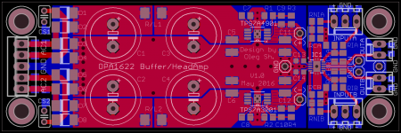
Attached is the updated version of the PCB. It can now be used in balanced, inverting or non-inverting configuration depending on which parts are populated. The PCB size is 9x3 cm now. I dropped 0603 size so now the smallest SMD parts are 0805. The space around the OPA1622 is tightly packed but the board can still be soldered by hand, even the OPA1622 if heated from below through the via in thermal pad.
I hope I did not compromise the design by allowing too many options.
Any comments and suggestions are welcome!
Regards,
Oleg
Attachments
While preparing the boards for manufacturing I decided to once again look carefully at the design shown in the previous post. One thing that I can't make totally clear to myself is the connection between signal and power GND planes. At the moment it is done at the left side of the IC1 (OPA1622) by introducing two vertical cuts in the otherwise continuous GND plane to avoid supply return currents traveling under the non-inverting opamp inputs. The question is if such a GND separation is really necessary? Or it is better to use a continuous GND plane all over? Could someone help me to resolve this issue?
Regards,
Oleg
Regards,
Oleg
I personally do continuous ground planes. Adding slots to force return currents onto a new pathway is basically just adding impedance to the ground return, and in my opinion that's never a good idea. If you're worried about the return pathway, you could change the connections to the output connectors so that the ground is now the pin closer to the centerline of the PCB
Hi John,
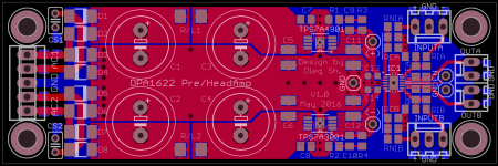
Thanks a lot for the hints! My concern about the return currents path is due to the increased currents in headphones amp application. If this would be an ordinary preamp with tiny currents involved it would not be a problem at all. So, I've taken your advice and removed the GND plane slots. I've also changed the output connections and placed GND pins close together near the center line of the PCB.
Regards,
Oleg
Attachments
Hasn't anyone designed a small board that will adapt the OPA1622 to a DIP-8 configuration so more people can try it?
Hopefully, whoever comes up with the board will also have the means to solder the IC to the board.
I would gladly pay for something like this since there's no way I would attempt to solder a VSON-10 package IC.
Hopefully, whoever comes up with the board will also have the means to solder the IC to the board.
I would gladly pay for something like this since there's no way I would attempt to solder a VSON-10 package IC.
Hi ammel68,
The idea of an adapter board has been discussed in the thread dedicated to OPA1622. Some people made an attempt in this regard but since OPA1622 requires GND pin connection for best performance it is impossible to use standard DIP-8 layout unless a compromise is made by connecting the GND pin of the OPA1622 to negative supply. Please follow the discussion in the dedicated thread for more details.
Oleg
Please understand that by "compromise" we're talking about a 3-6dB increase in distortion at 10kHz, it's still quite good performance and I use DIP adapters in the lab at TI for quick results if I'm not testing for absolute best performance.
The only place I'm aware of that is selling dip adapters for OPA1622 right now is akizuki denshi in Japan ‚n‚o‚`‚P‚U‚Q‚Q‚c‚h‚o‰»ƒ‚ƒWƒ…�[ƒ‹: ‘g—§ƒLƒbƒg �HŒŽ“dŽq’Ê�¤ “dŽq•”•i ƒlƒbƒg’Ê”Ì but I am not aware if they ship internationally.
Maybe I need to start a side business 😉
The only place I'm aware of that is selling dip adapters for OPA1622 right now is akizuki denshi in Japan ‚n‚o‚`‚P‚U‚Q‚Q‚c‚h‚o‰»ƒ‚ƒWƒ…�[ƒ‹: ‘g—§ƒLƒbƒg �HŒŽ“dŽq’Ê�¤ “dŽq•”•i ƒlƒbƒg’Ê”Ì but I am not aware if they ship internationally.
Maybe I need to start a side business 😉
Anyone with a PCB layout tool can repeat what Akizuki Denki did (see link below).
http://akizukidenshi.com/download/ds/akizuki/AE-OPA1622.pdf
And I am sure TI has all the capability of issuing a SOIC8 version, if they wish.
It all has to do with what demand is out there.
Judging from the responses here, I doubt it will yield very good return.
Patrick
http://akizukidenshi.com/download/ds/akizuki/AE-OPA1622.pdf
And I am sure TI has all the capability of issuing a SOIC8 version, if they wish.
It all has to do with what demand is out there.
Judging from the responses here, I doubt it will yield very good return.
Patrick
- Home
- Amplifiers
- Headphone Systems
- Universal buffer/headamp based on OPA1622