Oofda! It's been a crazy few days at work and coming home to fiddle with the this project has been a lot of fun.
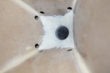
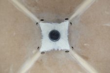
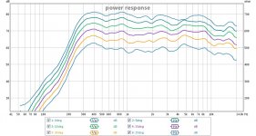
I tried a bit more filler using modelling clay and gave it a shot. It looks pretty good. I did power response measurements measurements every 5 degrees and it looks to have excellent constant directivity EXCEPT directly on axis (raw HF response, measurements are offset for clarity). At about 4khz there is a dip on axis that is not evident anywhere else. Perhaps this a result of using a compression driver with a convergent phase plug design rather than spherical. Are there any free tools available to make those fancy polar plots?
The crossover was tricky. You're right Tom, having more overlap would have made things easier. I ended up pushing the D220ti's down to a 1200hz 2nd order BW filter. The mids use a 1st order filter for high and low pass. I'm curious what kind of filters Red Spade is using in his design.
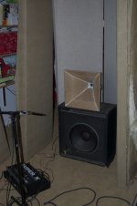
I set it up with an old Peavy 15" bass cab I had around and a behringer active crossover. This crossover setup didn't match great, but it was fun to listen to. The first thing I noticed was the transient response. I'm a drummer, and this is the closest I've heard recorded drums sounding like the real thing. I was battling all sorts of noise going pro +4 line level gear to the -10 minidsp back into +4 pro amps so that kind of spoiled things. For reference, I have a home studio with JBL LSR4328P monitors in a well treated control room. I'm excited to get them setup properly in my living room.
I have two pairs of 15" woofers That I've been holding on to: EV EVM15B-Proline's and McCauley 1560B's. The EV's are more efficient, the McCauley's go lower. Over the next few weeks I'll be finishing both horns and ordering another MiniDSP to properly manage the 15's and eventual do a multisub setup.
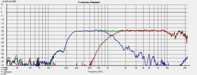
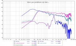
I tried a bit more filler using modelling clay and gave it a shot. It looks pretty good. I did power response measurements measurements every 5 degrees and it looks to have excellent constant directivity EXCEPT directly on axis (raw HF response, measurements are offset for clarity). At about 4khz there is a dip on axis that is not evident anywhere else. Perhaps this a result of using a compression driver with a convergent phase plug design rather than spherical. Are there any free tools available to make those fancy polar plots?
The crossover was tricky. You're right Tom, having more overlap would have made things easier. I ended up pushing the D220ti's down to a 1200hz 2nd order BW filter. The mids use a 1st order filter for high and low pass. I'm curious what kind of filters Red Spade is using in his design.
I set it up with an old Peavy 15" bass cab I had around and a behringer active crossover. This crossover setup didn't match great, but it was fun to listen to. The first thing I noticed was the transient response. I'm a drummer, and this is the closest I've heard recorded drums sounding like the real thing. I was battling all sorts of noise going pro +4 line level gear to the -10 minidsp back into +4 pro amps so that kind of spoiled things. For reference, I have a home studio with JBL LSR4328P monitors in a well treated control room. I'm excited to get them setup properly in my living room.
I have two pairs of 15" woofers That I've been holding on to: EV EVM15B-Proline's and McCauley 1560B's. The EV's are more efficient, the McCauley's go lower. Over the next few weeks I'll be finishing both horns and ordering another MiniDSP to properly manage the 15's and eventual do a multisub setup.
Attachments

Last edited:
I clicked on the link and it sent me to the sketchup web page from google. Cowans link worked fine. Have always wanted to try one of these builds but it seemed to complicated.
Nice! Trial and succes method always gives good results.
Can you imagine an unity horn with a AMT hf driver, rather then a compression driver ?
I think that would be the ultimate unity horn 😀
Can you imagine an unity horn with a AMT hf driver, rather then a compression driver ?
I think that would be the ultimate unity horn 😀
I clicked on the link and it sent me to the sketchup web page from google. Cowans link worked fine. Have always wanted to try one of these builds but it seemed to complicated.
Derp. Here's the zipped sketchup file. I guess there is a time-out for editing posts.
It's not super pretty, but it's useful. The important thing was generating the dimensions and miter angles for each piece.
Attachments
Thanks for that. The building process I think I could handle but drilling the correct size holes for said drivers seems like that would take me a very long time to figure out.
Some corrections (now that I'm not watching a movie and posting at the same time):
-The power response plot is both drivers with an earlier crossover. No EQ.
-I used an LR24 for the HF crossover, not a BW12.
I'll probably fiddle some more to get a lower order HF crossover to work. It will end up asymmetrical as I think the LR24 HF is the closest match to the Mid's slope with its 1st order filter.
At about 4khz there is a dip on axis that is not evident anywhere else.
I'm definitely not the guy to comment on the 4KHz issue expertly, but I'm obsessed with building a set of these horns and I came across this excerpt from another thread:
"When the new horn shape that Nick used was made, it also took a bit to get the kinks figured out. Where the mid holes are, there is a small impedance discontinuity (due to the change in cross section), making the holes as small as possible makes this as small as possible. At about 4 KHz, that location in the horn is governing the directivity in the 4 KHz area and that causes a reflection. This reflection causes the dispersion pattern to widen temporarily at 4 kHz which because the acoustic power spread over a wider angle produces a "hole" (the notch you saw) exactly on axis. This notch is not present off axis fwiw. The reflection can be eliminated (or at least its effects once the sound exits the mouth) by placing 4 small foam absorbers at the right location on the mouth and then the dispersion and amplitude response at 4 kHz are "fixed" without other impact. Even when not "fixed" the effect is minor and a narrower slice in frequency than one can discern."
It's attributed to Tom.
NYCone posted a quote about the dip;
While I don’t remember saying that precisely, it is right and like I explained somewhere here, he had filled in the corners more than we did. It would be worth going back and examining the shape of the upper range as you add the corner fill, while having a lot looks good, you may have gone past the optimum amount.
Jmorken, what are you using to figure out the crossover for these?
Remember when you have the crossover right, there is no (or little) phase shift through crossover, it looks like a single driver.
Best,
Tom
Is it possible for you to give as a direction in wich we have to search an apropiate solution for the crossover?
Elsewhere you'd mentioned TEF by Gold Line. Is that necessary for building a set of Unitys or Synergys, or can one use ARTA and the like?
Jmorken, what are you using to figure out the crossover for these?
Remember when you have the crossover right, there is no (or little) phase shift through crossover, it looks like a single driver.
Best,
Tom
I'm using trial and error measuring with REW and HOLM.
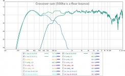
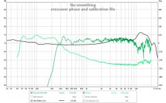
I think I've got the crossover figured out. By inverting the polarity of the mids and using 1st order filters all the way around, The phase of the passbands matches perfectly and I get an incredibly flat phase response through the crossover and less than 360 degrees of phase rotation all the way through the mid-high passband. This gives me an acoustic crossover at 900hz. I'm sure this is pushing the d220ti way to hard.
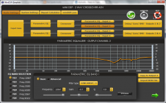
My challenge right now is voicing. I can get pretty measurements, but it honestly sounds awful. Maybe it's my measurement setup (i'm working mostly indoors) or microphone (my calibration file was not pretty). Maybe it's the d220. The power response I measured is weird, with the majority of the range falling off evenly except for the highest octaves. This is the opposite of what typically happens so I'm thinking it has to be how I'm doing the measurents. Attached also is the HF eq settings I'm using to get a flat response 5degrees off axis 1 meter away. Perhaps EQ this ugly should be an indicator that something else is wrong. I'm going to order a new mic that I feel I can trust and try to do outdoor measurements.
Attachments

Ruler flat does not sound very good under normal conditions.My challenge right now is voicing. I can get pretty measurements, but it honestly sounds awful.
If you have not done so yet you might want to try an averaged response around your listening position. Your measurement location might be a bit on the deceiving side of a true response.
A simple shelf at the right point in the response can do wonders.
A really well recorded piece on instruments you know well can be a good guide to realistic sound. I usually use acoustically picked up recordings that are some of my favorites. I enjoy classical so if that is your cup of tea I can recommend a few recordings if you want. But there are great examples of the recording art in many other types of music to.
bingo
I had a brilliant idea: why don't I measure something I KNOW sounds good and compare it to that. So I did near field measurements (1cm or less) of both drivers of my studio monitors. What it revealed is a constantly falling measurement response at about 3db an octave. I think "voicing" might have been an understatement 🙄
I promptly added a very wide shelf filter to the MiniDSP and VOILA it sounds like music. The horn sounds very nice - the 15" is far from dialed in.
Any idea what could cause this? I got the same results in REW and HOLM so it's not the software. I'm definitely getting a new mic.
Attachments
Last edited:
nice work jmorken! I'm working on a Synergy horn, the one that Gainphile posted pics of earlier. It's on my blog:
Red Spade Audio: DIY Synergy horn
(BTW Gainphile a little GTG pretty soon is on the cards)
One of the things I'm looking at is the design of the ports. In my sims I noticed that the length of the port has a big impact on both ends of the midrange response. Longer ports tend to lead to less out of band output above the roll off and reducing the length can also kill the bottom end extension - at least in my sims.
To get some nice directivity plots, Arta is a good one to use. I'm setting up a polar measurement turntable so I can measure properly outdoors.
At the moment it seems there is a lot of interest in DIY Synergy horns!
My next version will be 60 x 90.
Looks like you've made some great progress jmorken, I'll be following with interest.
Looking great. Happy to see your progress and I'm hoping it sounds wonderful.
I have been toying with a ribbon loaded version (high frequency is a ribbon) for quite a while. When it's done I'll post it.
I have been toying with a ribbon loaded version (high frequency is a ribbon) for quite a while. When it's done I'll post it.
I have been toying with a ribbon loaded version (high frequency is a ribbon) for quite a while. When it's done I'll post it.
I've also thought about this, after playing around with some Monoon planars in a waveguide setup (similar to the Neo 8). This worked really well. My concern with a ribbon/planar in a Unity/Synergy though is that with the LF drivers also loading the horn, the tweeter will be directly exposed to the LF wave traveling back up to the throat. A sealed tweeter should be excursion protected due to the back chamber, but with a ribbon I'm not sure this will be the case - an AMT style setup may or may not be different. Something like a Neo 3 with a sealed back chamber might be OK too.
Anyway, very curious about your results.
I ordered a new mic (Dayton EMM-6). The mic I was using was an old Goldline measurement mic I got from a friend. I figured once it was calibrated I should be good to go, but that hasn't been the case.
As far as finding the appropriate port length, I've been trying to find the balance between reducing out of band response and maximizing bandwidth to create a broad crossover region and minimize phase. I'd love to know more about your processing and resulting phase response. I'll be posting more results once my new measurement mic arrives (Thursday!).
Likewise 😀
I played around with this a lot in Hornresp before I built my horns and, just like a 4th-order bandpass box, you can change the size of your ports and maintain the same response by keeping the relationship between the area and length constant. The limiting factor then becomes port velocity and the distortion/compression that results from too small a port.One of the things I'm looking at is the design of the ports. In my sims I noticed that the length of the port has a big impact on both ends of the midrange response. Longer ports tend to lead to less out of band output above the roll off and reducing the length can also kill the bottom end extension - at least in my sims.
As far as finding the appropriate port length, I've been trying to find the balance between reducing out of band response and maximizing bandwidth to create a broad crossover region and minimize phase. I'd love to know more about your processing and resulting phase response. I'll be posting more results once my new measurement mic arrives (Thursday!).
Looks like you've made some great progress jmorken, I'll be following with interest.
Likewise 😀
I've also thought about this, after playing around with some Monoon planars in a waveguide setup (similar to the Neo 8). This worked really well. My concern with a ribbon/planar in a Unity/Synergy though is that with the LF drivers also loading the horn, the tweeter will be directly exposed to the LF wave traveling back up to the throat. A sealed tweeter should be excursion protected due to the back chamber, but with a ribbon I'm not sure this will be the case - an AMT style setup may or may not be different. Something like a Neo 3 with a sealed back chamber might be OK too.
Anyway, very curious about your results.
I'm building a Unity horn with a ribbon at the Apex.
Mine is designed to be pretty, it's going in my bedroom.
It's going to be an iPod dock.
Audio Psychosis • View topic - an iPod Dock for the Psychotic
- Status
- Not open for further replies.
- Home
- Loudspeakers
- Multi-Way
- Unity Horn - budget drivers, active x-over